Trigger logger
enable trigger logger
Enable the built-in trigger logger.
sample count
The sample count to use, nothing will be showed before the amount of sample count of inputs has been received.
logging mode
Specifies which input to use as the trigger source.
TRIGGER, HOME/CAM and all available DIN signals are able to be logged.
Note: The trigger logger will ONLY log the input you have selected.
Result
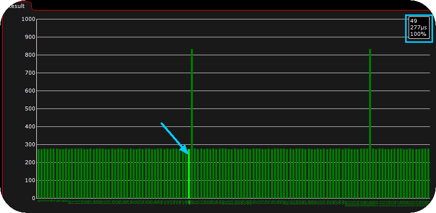
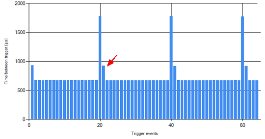
An example result from a 60-2 missing tooth trigger wheel, hover the mouse over the chart (when logger is paused) to get more information in the top right corner.
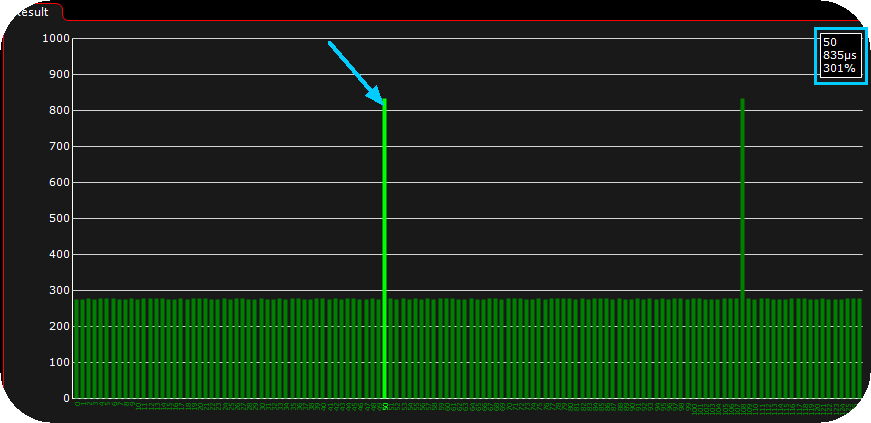
Here the "missing tooth" marked in the logger, and the top right corner gives us some valuable information like the tooth number (counted from 0 to max sample count), the time between two teeth.
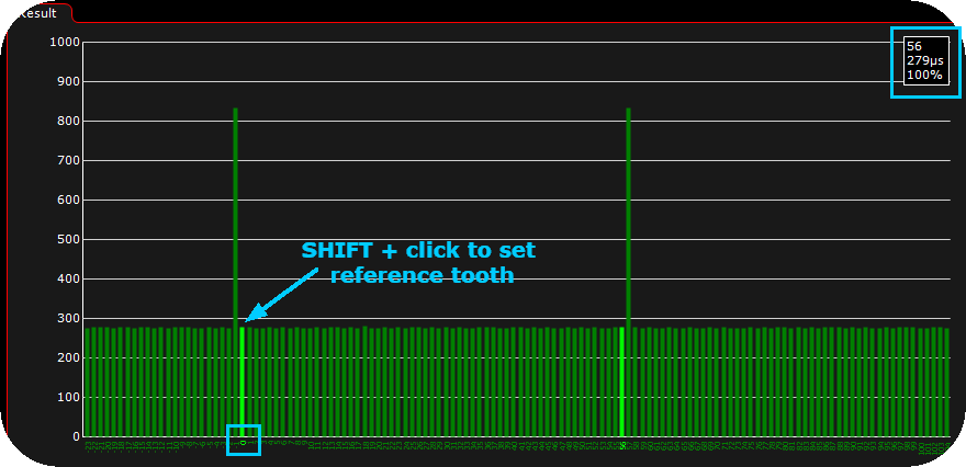
Press SHIFT and do a mouse click on the reference tooth you want. Used to easily calculate the number of teeth.
Note: The above "%" value can be summed up like this with an example: "Percentage of the previous gap. example above 301% means the gap is 3 times longer than the previous gap, or 2 missing teeth. You may think that means 3 missing teeth, but remember it is the "normal gap plus the missing tooth gap" that equals 3":
GREEN = OK
YELLOW = There is a trigger issue.
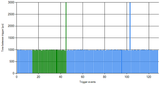
A gap in the trigger log view indicates that some data is missing because the RPM is too high to transfer it all over the USB connection. This is not a trigger problem and is nothing to worry about. When analyzing the data, just keep in mind that any number of teeth in this gap may be missing.
History
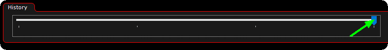
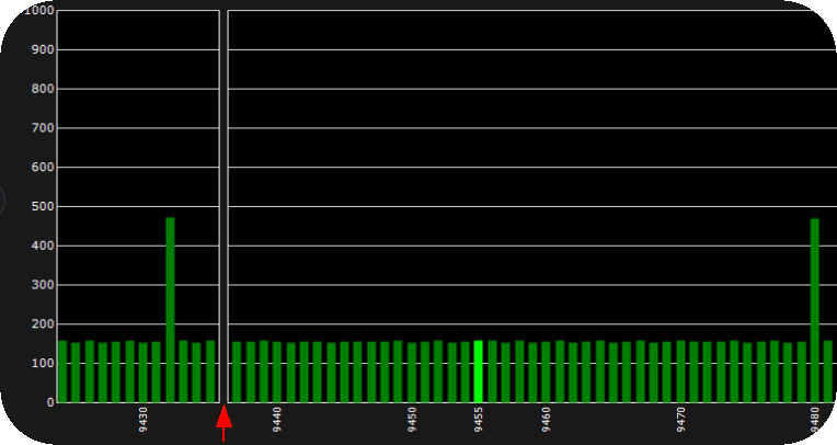
The history slider can be used to browse thru the history of signals (when the trigger logger is stopped of course).
The trigger logger can be used to:
•Tell what pattern the trigger wheel on the crank and cam has.
•See trigger problems caused by compression, bad trigger wheels, interference etc.
The trigger logger graphs the times (in microseconds) between each trigger signal received by the ECU. For this to show reliable results the trigger inputs need to be set up properly for the ECU to correctly trigger on the inputs.
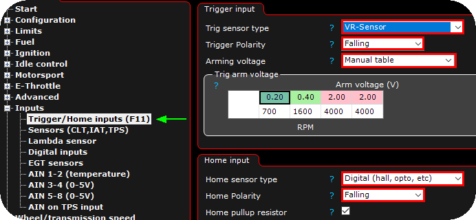
The Trigger Logger doesn't care at all about the trigger system or its settings, just the trigger inputs (the Trigger input and Home input sections).
Note: Green and Blue mean the ECU doesn't have any trigger problems (but there could still be problems it's not seeing). Orange indicates some problem.

Example of a good trigger pattern.
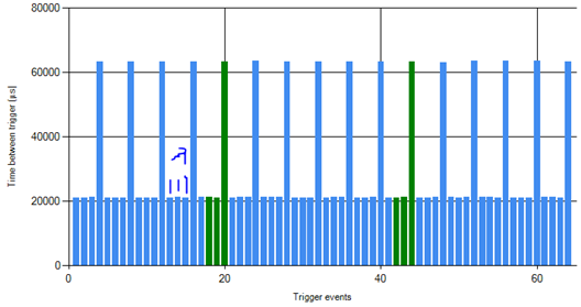
In the above image we can see that it has a pattern of 3 short and 1 long pulse. Remember that these are the times between the trigger signals. What would this wheel actually look like? From the "lots of short and one long", we can conclude that it's a missing tooth wheel.
The missing gap is about 3 times as long as the regular teeth. That means that there are TWO missing teeth (if were ONE missing tooth the time would be about 40000µs).
The total number of teeth including the missing would be 3(the short ones)+1(the long one)+2(the missing ones), so 6 teeth.
This pattern is 6-2.
Example of a trigger loggers with problems
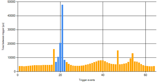
The small wave in the signal is the engine compression, the engine slows down a little during compression (which is totally fine for the ECU). BUT, there's a lot of triggers that are too long and it doesn't look like a pattern.
What's happening here is that the arming voltage is set to high and the ECU "misses" some of the triggers, so it registers several short signals as one long. This is not going to work.
The tooth after the missing is a little longer than expected. This is probably caused by incorrect polarity.
A good looking 60-2 trigger logger (57 short, 1 long, about three times longer than the other teeth)
This is when running, when cranking there's usually more variation in the pattern.
If the trigger pattern here looks irregular or has spikes and gaps in it, there's no way for the ECU to "sync" to the pattern and register RPM. Before continuing and trying to set up the trigger system (60-2 etc), we would need to figure out what the problem with the input signal is.