warning/information
Warning
•Incorrect settings of the injection staging system can cause the engine to run lean.
•Double-check all settings and test the engine under controlled conditions.
•Peak-Hold injectors can only be used as secondary's on MaxxECU REV7 units and above.
General for staged injection
•The secondary injectors are set as "Secondary injector".
•Injection pattern is the same as the primary injectors.
•"Secondary injector 1" opens with INJ 1 and so on.
•Depending on number of injector outputs on your MaxxECU, injectors might be connected in parallel.
injector staging settings
Staging mode: Auto transition
When the primary injectors are maxed out, MaxxECU opens the secondary injectors.
The primary injectors will continue to inject fuel together with secondary injectors.
Tuned as usual, the transition is handled automatically by the MaxxECU.
Staging mode: Manual control of secondary injectors (extra fuel table 1)
The amount of injected fuel is controlled by "extra table 1" (select secondary fuel amount for this table).
The injected fuel on the secondary injectors is only controlled by this table. All enrichment are added to the primary injectors only.
This mode is suitable for adding additional fuel when the primary injector capacity is to low, or when injecting an ADDITIONAL fuel/coolant to an engine (such as water/methanol).
Note: Not suitable for dual fuel setups, as some fuel is still added by the primary injectors.
Staging mode: Primary/secondary injector changeover (extra fuel table 1)
"Extra table 1" controls the distribution of fuel between the primary and secondary injectors. The amount of fuel is controlled by the VE-table.
0% means all fuel will be added by the primary injectors, 100% will add all fuel with the secondary injectors.
This can be used for trumpet mounted secondary injectors, or dual fuel/fuelsystem setups. Secondary injector fuel and injector size can be different than the primary, the ECU will calculate the correct fuel amount automatically.
50% means that the primary and secondary injectors deliver the same amount of the total required fuel volume, not that they have the same duty cycle.
The injector opening time is also accounted for, but that only has a minor effect here.
Note: It is very important that the opening time and the flow is correct to give a linear transition.
Min secondary pulsewidth
Specifies the minimum secondary pulsewidth, used to prevent low secondary injector opening times.
If the required secondary injector pulse width is below this point, the secondary injectors will stay off and fuel will be delivered using only the primary injectors (including the amount calculated to be delivered by the secondaries). Once the calculated secondary pulsewidth is higher than this value, fuel will be delivered using both primary and secondary injectors.
fuel type
Fuel stoich AFR
Specifies fuel type used on engine.
•Gasoline (14.7)
•E100 (9.0)
•E85 (9.7)
•E75 (10.2)
•Methanol (6.4)
•flex fuel (requires ethanol sensor)
•Custom setting
density correction
Fuel Density correction adjusts the fuel and fuel flow calculations to account for changing fuel density. If not used the fuel density is assumed to be 750kg/m3.
Note: just available when the above fuel stoich afr is set to custom setting.
Example, custom fuel stoich AFR
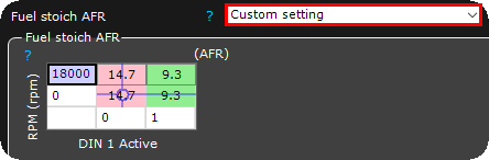
You can even create your custom stoichiometric ratio based on any X or Y axis, in the above example we have configured a switch wired to the digital input 1, which can be used to switch between petrol or E85 VE calculations.
secondary injector settings
Injector
Specifies installed injector type.
Note: If your injector is missing, please use "Used defined" and enter correct values.
Peak-Hold drivers
Peak and Hold drivers MUST be enabled for low impedance(below 8 ohms) injectors, and disabled with high impedance injectors (saturated).
Peak current
Specifies "peak" current which opens the injector.
3000mA = 3A which is default and used by most injectors.
Current above 5A per output is only allowed with 2 injectors per output.
Note: MaxxECU rev6+ and higher supports higher peak current, up to 8A.
Peak extension time
Only available for the GEN2 platform.
Peak extension holds the "peak" current for a fixed time before switching to "hold" current. Some injector manufacturers recommend this to ensure the injector is fully open before switching to hold current.
Use 0ms for most injectors. This minimizes heat in the injector and ECU. Use 1ms for large (300lbs/hr+) injectors at elevated fuel pressures, or when the injector manufacturer recommends a "peak hold" time.
This only affected the way the current to the injector is regulated; it does not affect the fueling.
Peak extension time Example
14ms fuel pulse with with 6A peak, 2A hold settings (same in both and below examples). (Green = Injector current, Blue = Voltage)

Example with a 2ms extension, the current is held at 6A for 2ms after it has reached 6A. Then it's decreased to 2A.

Example without an extension (0ms), the current is decreased to hold current as soon as the peak current is reached.
* Our injector drivers use a higher flyback voltage during turn-off, which forces the current in the injector coil to decay faster. This improves injector closing speed.
Hold current
Specifies hold-current for injector.
1000mA = 1A works for most injectors.
Injectors per output
Adjusts the injector drivers for the load.
MaxxECU PRO, RACE and V1 (rev7+) can use max 2 Peak-and-Hold injectors per output.
All MaxxECUs can use max 3 high resistance injectors per output.
Injectors per cylinder
Adjusts the fuel calculations to account for the fuel flow per cylinder.
Injector flow settings
Note: most fuel injectors are flow tested with heptane liquid, our preset values is coming from our own flow bench where we use E85, which might give a 5-10% difference in the flow.
injector flow tracking
Note: Only visible when injector is set to user defined.
•Fixed flow with default pressure compensation - The ECU uses a built-in fuel pressure correction for the entered injector flow. The 100% values are at 3 bars, if the fuel pressure is lower, the injector flow is increased (pulse widths are decreased as a correction) as an example.
•flow/pressure list - The ECU does NOT use any built-in pressure correction. All pressure vs. flow is done via the data entered in the Injector flow table that shows up. This is what you would use if you have data for the flow rates at different pressures. The ECU always uses the RT-value Primary(or secondary) fuel pressure as a source for the pressure correction. How this value is calculated depends on the Fuel pressure tracking setting below.
•flow table - The ECU does NOT use any built-in pressure correction. All pressure vs. flow is done via the data entered in the Injector flow table that shows up. This is what you would use if you have data for the flow rates at different pressures or any other available axis source.
This flow table supports an 4D.
Injector flow
Note: Only visible when injector is set to user defined.
Specifies injector flow in cc/min at 3bar fuel pressure.
Fuel pressure tracking
•Fixed value - The fuel pressure follows the MAP at a 1:1 ratio. The ECU assumes that pressure across the injector is always that's entered in the Fuel pressure setting.
•Fixed value, fixed pressure - The fuel pressure does NOT track the MAP. The ECU assumes the fuel pressure to be Entered-Fuel-Pressure-MAP+BARO. So at vacuum when the differential fuel pressure is higher than at load the ECU assumes the fuel pressure is higher, calculates a higher flow rate, and decreases the injector pulse widths.
•fuel pressure sensor 1/2 tracking - The ECU uses the actual sensor value to correct the flow. The sensor is setup as class=Fuel pressure sensor X in kPa. The tracking type offset and target pressures are setup under the Fuel pressure sensor X page.
Note: You want the "Primary fuel pressure" RT-value to read 0kpa with no pressure, and 300kpa at 3bars positive fuel pressure etc.
Note: Fuel pressure deviation tracking (without fueling correction) can be done without this enabled here.
Fuel pressure
The specified fuel pressure when the above fuel pressure tracking is set to fixed value.
Note: Not used when fuel pressure sensor 1/2 tracking above is active.
injector deadtime settings
Injector dead time
Injector dead time at different voltages. "Dead time" is the amount of time it takes for the injector to transition from closed to open.
Pulsewidth adder
Injectors become Non-Linear at very low pulsewidth. This table allows you to compensate for this. These values can be supplied by the injector manufacturer.
Video example

MaxxECU Academy - Staged injection