Bipolar stepper motors can only be driven by the bridge-outputs GPO 11,12,13 and 14.
Unipolar stepper motors can be driven from any outputs.
MaxxECU MINI/STREET/SPORT controls only Unipolar stepper motors (5/6 wires), but RACE and PRO can control 4-wire also (see below).
Note: The idle stepper "homes" on power up when no ECU power hold relay is setup (no Ignition key input). When doing a "power on home", it closes the number of steps set, then goes to whatever position the idle control needs. When doing a "power off home" (with power hold), it closes the number of steps set, then open 100%. On the next power up it goes to whatever position the idle control needs directly.
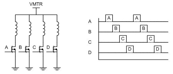
In unipolar stepper drive, the stepper is made out of four coils connected in a star configuration with a center tap.
The center tap is connected to the positive power supply terminal and each one of the four windings is connected by
means of a switch to the GROUND terminal. In the most typical full step mode, each switch is enabled independently
from the others, so current flows from Power to GND. Since current only flows in one direction, a single electromagnet
polarity is generated. Hence, the name Uni-Polar. The actuation of a Unipolar Stepper Motor is quite simple. The idea is
that by polarizing each subsequent electromagnet, the rotor is moved one step further.
Hence the sequence is very important. Reversing the correct sequence will result in the motor rotating in the opposite direction.
4-wire stepper
4-wire stepper motors can also be used with RACE/PRO built-in H-bridge drivers on GPO 11-14 (even if this output is labeled 5/6 wire)
MaxxECU outputs "ABCD" on each output.
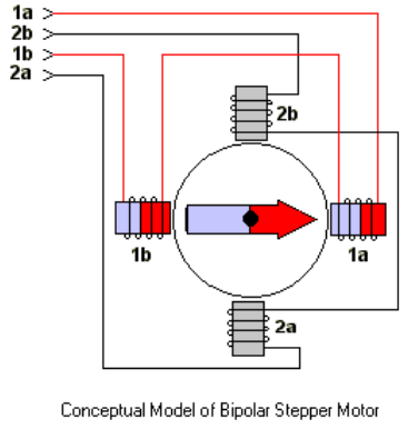
4-wire stepper motor example.
1a -> GPO11 -> Stepper motor A setting
2a -> GPO12 -> Stepper motor B setting
1b -> GPO13 -> Stepper motor C setting
2b -> GPO14 -> Stepper motor D setting
The driving stages
Stage 1: GPO 11 = 12V, all other grounded.
Stage 2: GPO 12 = 12V, all other grounded.
Stage 3: GPO 13 = 12V, all other grounded.
Stage 4: GPO 14 = 12V, all other grounded.
The two separate coils are driven alternately, one coil is set as "A" + "C" and the second as "B" + "D"
How to test
•Set number of steps to 100 (1% = 1 step)
•Use the idle control test mode
•By setting idle stepper duty test to 1,2,3,4 and so on, the stepper motor will take one step at a time.
•By testing different combination of settings, you can find out which is correct when motor is rotating in the right direction and are stable.