Function name
Description
Assign a descriptive name to the output or function. This name is displayed throughout MTune PC-software and MDash Android app, making it easier to identify and distinguish the function in configuration menus, monitoring views, logs, and dashboards. Use clear, meaningful names.
Output enabled
Enables or disables the output. When Disabled, the output is forced to its inactive condition while all settings remain available for configuration and testing without affecting the physical output. For inverted outputs, the physical output will remain active when disabled, as the activation conditions are treated as false.
•Enabled - The output operates normally according to its configured conditions.
•Disable - The output is disabled while all settings remain editable. The activation conditions are forced false, meaning inverted outputs remain physically active.
Conditions
Variable
Selects the input value that the condition monitors. The selected variable is continuously compared against the configured threshold using the chosen comparison operator (e.g. Greater Than or Less Than) to determine whether the condition is true or false.
Examples of variables include coolant temperature, engine RPM, oil pressure, throttle position, MAP, battery voltage, and other available ECU channels.
comparison operators
Selects how the variable is compared to the threshold value to determine when the condition becomes true.
Hysteresis
Hysteresis prevents an output from rapidly switching on and off when the measured value is close to the activation point.
It does this by using different values for turning the output ON and OFF, creating a small deadband between the two switching points.

Example: The output turns ON above 90°C and OFF below 85°C, creating a 5°C hysteresis deadband.
Output configuration
Output function
Selects how the conditions are combined to control the output. Choose a predefined logic mode or create a custom Boolean expression.
Custom Expression
Enter a custom Boolean expression to define advanced output activation logic.
Available variables: A, B, C, D, E = Input conditions.
Operators:
& = Logical AND.
| = Logical OR.
! = Logical NOT (inverts the condition).
( ) = Parentheses to control the order of evaluation.
Note: AND and OR have the same precedence. Expressions are evaluated from left to right unless parentheses are used to specify the evaluation order.
Examples:
A & (B | C) - The output is active when A is true and either B or C is true.
(A & !B) | (!A & B) - The output is active when either A or B is true, but not both (exclusive OR).
Available for User Outputs 1-5 and Internal Outputs 1-5.
turn on delay
Specifies a delay time (in seconds) to be used when condition (s) are active before actually triggers this function.
Turn off delay
Specifies a delay (in seconds) before the function is disabled after the condition(s) become inactive.
Output
Selects how the output behaves when the configured conditions change.
•Normal - The output is active while the conditions are true.
•Inverted - The output logic is reversed. The output is active while the conditions are false and inactive while the conditions are true.
•Latch, Push: ON / Push: OFF - Each activation toggles the output state. One push turns the output ON, the next push turns it OFF.
•Latch, Push: ON / Long Push: OFF - A short activation turns the output ON. The output remains latched until the activation is held long enough to turn it OFF.
Output Flash
Selects whether the output should flash instead of remaining continuously ON or OFF.
•NO - No flashing. The output follows its normal state.
•Slow flash when output active - The output flashes slowly while active.
•Fast flash when output active - The output flashes rapidly while active.
•Slow flash when output inactive - The output flashes slowly while inactive.
•Fast flash when output inactive - The output flashes rapidly while inactive.
Note: Flash modes are mainly intended for physical outputs driving indicator lamps or LEDs.
additional INput to control
Input function
Selects which MaxxECU digital input function is controlled by the configured conditions. The selected input is activated when the conditions are true and deactivated when they are false.
Examples
Activate a low oil pressure warning light

1. Activate an User output on a MaxxECU output config (Outputs --> Output config), in the above example we use GPO 1 where we have a warning light wired.
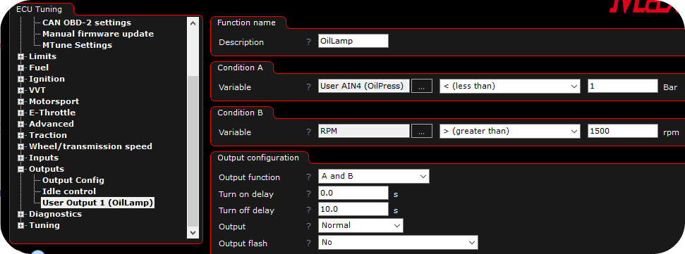
2. User Output 1 is shown in Outputs --> Output Config. The above settings will trigger the output when Oil Pressure is less than 1bar, but only if 1500 RPM or more. Preferable use the advanced warning system instead for similar features.
Activate a on/off cam solenoid in different RPM ranges
1. Activate an User output on a MaxxECU output config (Outputs --> Output config), in the above example we use GPO 1 where we have the cam solenoid wired.
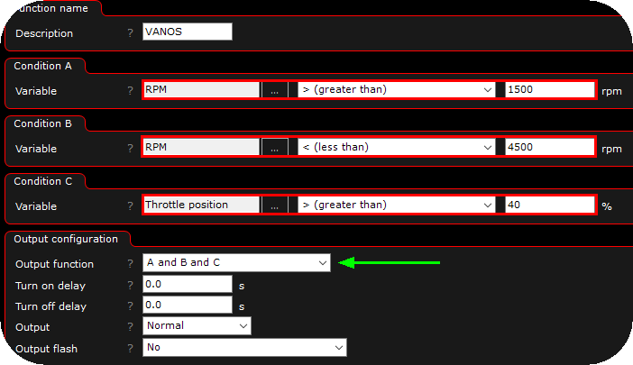
2. In the above example the BMW M50 VANOS solenoid is activated between 1500 and 4500RPM WHEN the throttle position is above 40%.
Note: User output might be used to control on/off VVTi systems called VANOS, VTEC.