Note: The trigger oscilloscope does ONLY works with the physical TRIGGER and HOME inputs, if you have for example set a digital input to Trigger, CAM/HOME or Trigger, HOME+CAM dual sensor, cam sensor, nothing will be showed on the HOME!
Trigger/home oscilloscope
sample time
Specifies the amount of time the system actually samples data and displays it on one frame.
When using the scope it's critical to use a sampling time that matches the expected frequency of the signal. If the sampling time is too long for the RPM/signal frequency it just looks like garbage because the ECU samples to slow to read the signal properly.
A sign that tells that the sampling time is too long is that there are "crosses" (the small trigger marks) that doesn't match the waveform displayed, or that the waveform is too compressed. When the sampling time is too long it can't be used to tell anything.
Note: Always start with a low sample time and increase it until the data you want to see is on the screen.
Start mode
Specifies how the trigger oscilloscope should start capturing signals.
•Continuous - Will continuously draw the captured data.
•Single - Captures a single image and stops the capture.
Trigger source
Specifies how the oscilloscope should be started (triggered).
•Direct - Will start capturing data when start measurement button is pressed.
•Trigger home signal - Will start capturing data when a HOME/CAM signal has been detected.
•Trigger error - Will start capturing data when a trigger signal has been detected by the system.
•Cylinder TDC - Will start capturing data when the specified (CYLINDER # below) is at TDC.
Cylinder #
Specifies which cylinder to be used to start the sampling when the above TRIGGER SOURCE = CYLINDER TDC.
Result
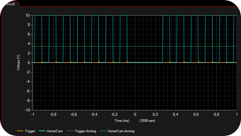
An example result from a 60-2 missing with a digital TRIGGER signal.
History
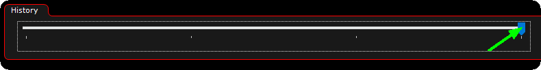
The history slider can be used to browse thru the history of signals (when the oscilloscope is stopped of course).
The scope is used to:
•Check the input voltages of both digital and VR-sensors.
•Set the arming voltages for VR-sensors.
•Check the polarity of VR-sensors.
•Check for zero-crossing problems on VR-sensor.
•Check the relationship between the Crank and Cam sensors in some special cases (multitooth+home like the 2JZ and similar triggers).
The scope is NOT the tool to tell anything about the actual pattern on the trigger wheels. It can be used to tell basic stuff like if the inputs are swapped, but to analyze the patterns we use the Trigger Logger.
The trigger logger can be used to:
•Tell what pattern the trigger wheel on the crank and cam has
•See trigger problems caused by compression, bad trigger wheels, interference etc.
See, Trigger Logger for more information about the important trigger logger.
How to use the trigger oscilloscope
Examples of what settings might be used to set by using the built-in trigger oscilloscope.
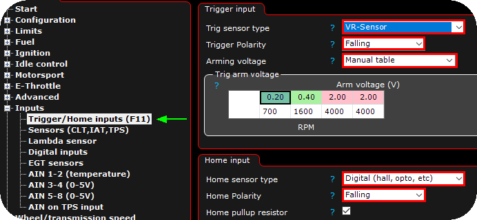
1. Use the Trigger Oscilloscope to set the Trigger Input and Home Input sections. (Digital/VR, polarity and arming voltages).
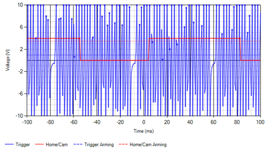
Note: When cranking, start at 200ms, that's about 1 revolution at normal cranking speed (if the data is to compressed try lowering the time (necessary for wheels with lots of teeth)).
In the above we can see that the Trigger (crank) is a VR-signal and the HOME/CAM is a digital signal.
From the VR-signal we can tell:
•It has lots of voltage, we can set the ARM voltage high to make it less sensitive to interference.
•The polarity is FALLING, because that's it that's the fastest "edge" during the missing gap (rises slowly, falls fast)
From the digital signal we can tell:
•The voltage from the sensor is OK (it needs to be above the dotted red line, and then fall to about 0V).
•The polarity if digital signals can't often be determined from the scope.
Digital signal polarity:
• There are cases where it should be the edge farthest away from a crank wheel edge.
• In some cases, it's dependent on the selected Trigger system.
• In most cases, it doesn't matter for digital signals.
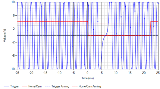
Common problems that can be seen in the scope:
Sampling time to long for the signal, looks compressed and uneven.
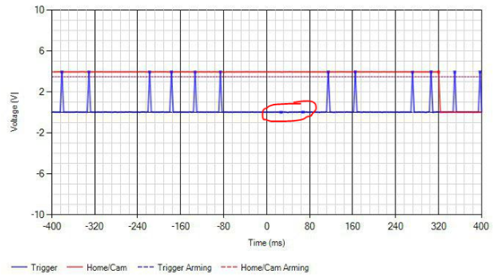
Sampling time to long, trigger-dots but no matching waveforms.
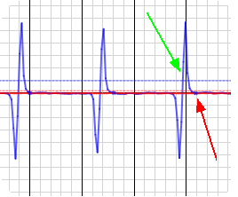
Incorrect polarity, it triggers on the falling edge, but it should be on the rising edge.
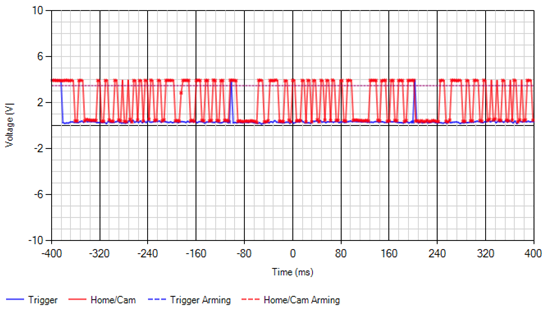
To long sampling time, many trigger dots that doesn't match the waveform. There's also more signals on the CAM input than on the CRANK, indicating that the CAM and CRANK inputs most likley are swaped.
See Trigger problems which describes this.