See, SENT protocol input digital input function E-Throttle bodies wiring.
Note: SENT sensors should always be connected to either DIN 1 or DIN 2 on the MaxxECU.
Note: If SENT is used on either DIN 1 or DIN 2, any other speed input (wheelspeed, driveshaft speed etc) is not recommended on either DIN 1 or DIN 2, any other digital input function can be used though.
DIN 1 = SENT1.
DIN 2 = SENT2.
Note: The SENT protocol is supported by all MaxxECU GEN1 units, currently not support by the GEN2 platform.
Sent protocol input x
sent mode
•32-bit - standard bit size.
sent type
SENT standard to use. They use different CRC-calculation, only one of them will work.
•SAE J2716 JAN2010.
•SAE J2716 feb2008 (legacy).
sent tick
Specifies the SENT tick length. 3µs is common.
Needs to be determined for each sensor used.
Use an oscilloscope to find the "sync" pulse, find the fall-to-falling edge time of that and divide by 56 = SENT tick.
Example: GM throttle bodys: 3µs.
Note: SENT allows for 20% variation for tick length.
channel x data
CH order
Order of the nibbles in this channel. Change this if the data looks erratic.
CH bitmask
Defines which bits in the CAN data stream are used for the TPS signal by masking out unused or non-TPS bits. This is required for some electronic throttle bodies where additional data, such as counters, is transmitted in the same byte.
Note: Newer Ford Mustang electronic throttle bodies include an 8-bit counter together with the backup TPS signal. The CH Bitmask must be configured to filter out the counter bits and extract only the TPS value.
CH min data
MIN data input value (0-4095). See SENTx CHx data RealTime Data value.
CH max data
MAX data input value (0-4095). See SENTx CHx data RealTime Data value.
CH min value
MIN output value in real unit. Ex 0 (%).
CH max value
MAX output value in real unit. Ex 100 (%).
CH Name
Channel descriptive name.
CH unit
Channel descriptive unit.
CH Destination
Analog input channel to send the data to.
Example using the GM 12678223 E-Throttle body
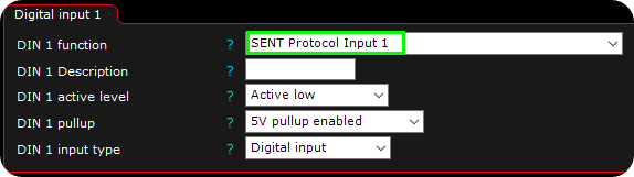
1. Activate the sent protocol input x on either DIN 1 or DIN 2.
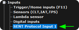
2. A new setting page is available under inputs.
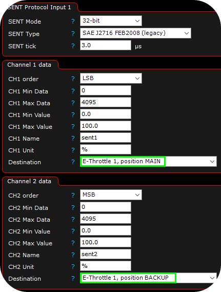
3. Data to get position inputs from the GM 12678223 E-Throttle.
Example using the newer Ford E-Throttle body
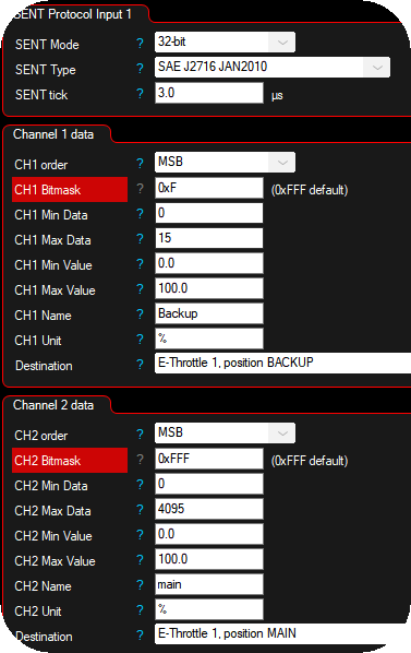
Channel 2 contains the primary TPS signal. Channel 1 contains an 8-bit counter and a 4-bit backup TPS signal. The backup TPS has very low resolution but is sufficient for redundancy. Set the error threshold accordingly.
Note: Newer Ford Mustang electronic throttle bodies require the CH Bitmask setting to filter out the counter value present in the data stream.
The rest is like normal a regular E-Throttle setup, besides that one single Digital input (DIN 1) is reading the E-Throttle position inputs and sent it to a "virtual" analog input in MaxxECU.