The MaxxECU RACE adapter for Audi with ME 7.5 ECUs can only be used with MaxxECU RACE.
(for information on the old MaxxECU V1 + E-Throttle module adapter, click here)
Vehicle cover list
Vehicle |
Engine code |
Year |
LSU sensor |
Note |
Audi A4 |
APU |
1999 |
External sensor needed |
|
Audi S3 |
BAM |
1999 - 2003 |
Uses stock LSU 4.2 sensor |
|
Audi S3 |
AMK |
2000-2003 |
Uses stock LSU 4.2 sensor |
|
Audi S3 |
APY |
1998-1999 |
External sensor needed |
|
Audi S3 |
AUL |
1999-2001 |
External sensor needed |
|
Golf IV GTI |
AUM/AUQ |
2002+ |
Uses stock LSU 4.2 sensor |
|
Skoda Octavia RS |
AUQ |
2000-2005 |
Uses stock LSU 4.2 sensor |
|
Seat Leon |
AMK/ARY/AUQ |
2002+ |
Uses stock LSU 4.2 sensor |
|
Seat Leon |
ARY |
2000-2004 |
Uses stock LSU 4.2 sensor |
|
Seat Leon |
AJQ |
2001+ |
Uses stock LSU 4.2 sensor |
|
Audi TT |
APX |
1999 |
External sensor needed |
|
Audi TT |
APX/APP/AJQ |
2000+ |
External sensor needed |
|
Audi TT |
AUM/AUQ/ARY/BAM |
2002+ |
Uses stock LSU 4.2 sensor |
|
Audi A4 |
BEX |
2002 - 2005 |
Uses stock LSU 4.2 sensor |
Note: No auto transmission support on any model!
Note: Not all ME 7.5 have CAN pinned in the ODB connector for ODBII functionality.
Control options
Options |
OEM ECU PIN |
MaxxECU IO |
RACE |
Note |
E-Throttle |
117/118 |
GPO 11/12 |
Yes |
|
Boost solenoid (OEM) |
104 |
GPO 1 |
Yes |
|
VVT solenoid |
115 |
GPO 2 |
Yes |
|
Electrical thermostat |
116 |
GPO 3 |
Yes |
Only on some models (A4, BEX) |
Canister |
64 |
GPO 4 |
Yes |
|
Fuel pump |
65 |
GPO 5 |
Yes |
|
IAC cutoff valve |
105 |
GPO 6 |
Yes |
|
Tachometer |
37 |
GPO 8 |
Yes |
|
Main relay |
21 |
INJ 5 |
Yes |
|
Error light |
47 |
INJ 6 |
Yes |
|
Secondary air pump |
66 |
INJ 7 |
Yes |
|
FAN (PWM controlled) |
24 |
INJ 8 |
Yes |
Only on some models (A4, BEX) |
Knock sensors (OEM) |
106,107 |
KNOCK1, KNOCK2 |
Yes |
|
Vehicle speed |
54 |
DIN 1 |
Yes |
Also from CAN, Audi ME 7.5 CAN |
Clutch switch |
39 |
DIN 2 |
YES |
|
EPC light |
48 |
- |
||
Intake air solenoid |
9 |
- |
|
|
Instrument cluster/ABS |
|
YES |
||
Traction button |
|
YES |
||
Fuel consumption |
81 |
- |
||
Bluetooth (MDash) |
|
- |
Yes |
|
EGT option |
|
- |
Yes, direct |
6 EGT direct in harness |
Plugin adapter description
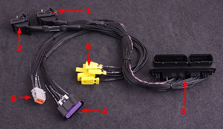
1 |
MaxxECU RACE CMC connector 1 |
2 |
MaxxECU RACE CMC connector 2 |
3 |
Vehicle harness adapter |
4 |
16-pin extra connector |
5 |
8-pin DTM connector (for external WBO) |
6 |
MaxxECU built-in EGT (1-6) mini-k connectors |
ECU location and installation
Stock ECU is located in engine bay on driver side or under the windshield plastic cover, depends on which vehicle you have.
1.Remove the plastic guard where the ECU is located.
2.Disconnect battery from vehicle.
3.Remove and disconnect stock ECU from vehicle harness.
4.Install MaxxECU adapter harness.
5.Route the included MaxxECU MAP-sensor hose to the intake manifold and connect into the MaxxECU.
6.Route wide band lambda cables to exhaust system, install lambda sensor in exhaust and wire the lambda sensor as instructed below if your vehicle not have a stock LSU sensor(s) mounted from factory (see vehicle cover list on the top if this page).
Note: MaxxECU RACE plugin ECU kit, might not fit into the standard plastic ECU box. Make sure to mount the ECU away from heat or water!
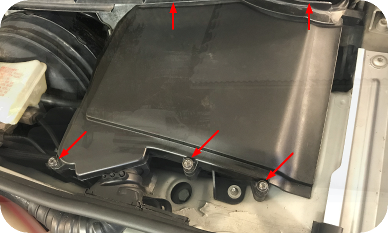
Remove the plastic cover where the stock ECU is located, 5pcs T27 screws.
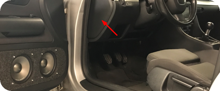
Remove the left side fuse box cover.
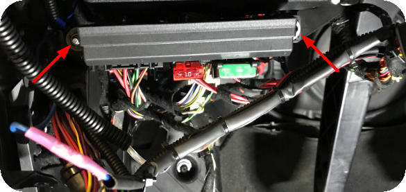
Remove the above fuse and relay central, fastened with 2pcs 10mm screws.
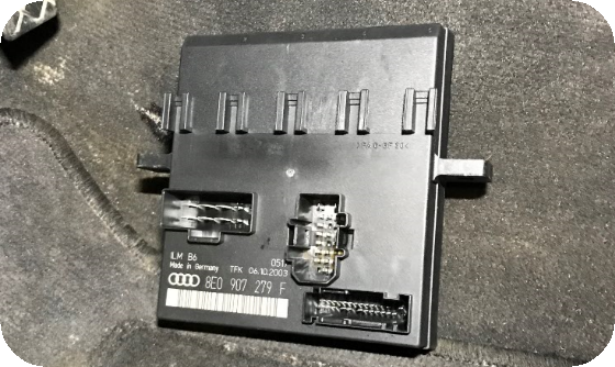
The removed fuse and relay central.
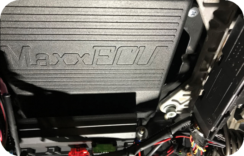
MaxxECU RACE fits perfectly between the fuse and relay central and the steering column. Some modification needs to be done to a plastic relay holder and needs to be moved away.
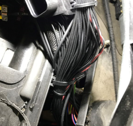
Route the adapter harness thru the passage down to MaxxECU RACE.
Note: Please install the CMC connectors in MaxxECU RACE before securing the RACE unit.
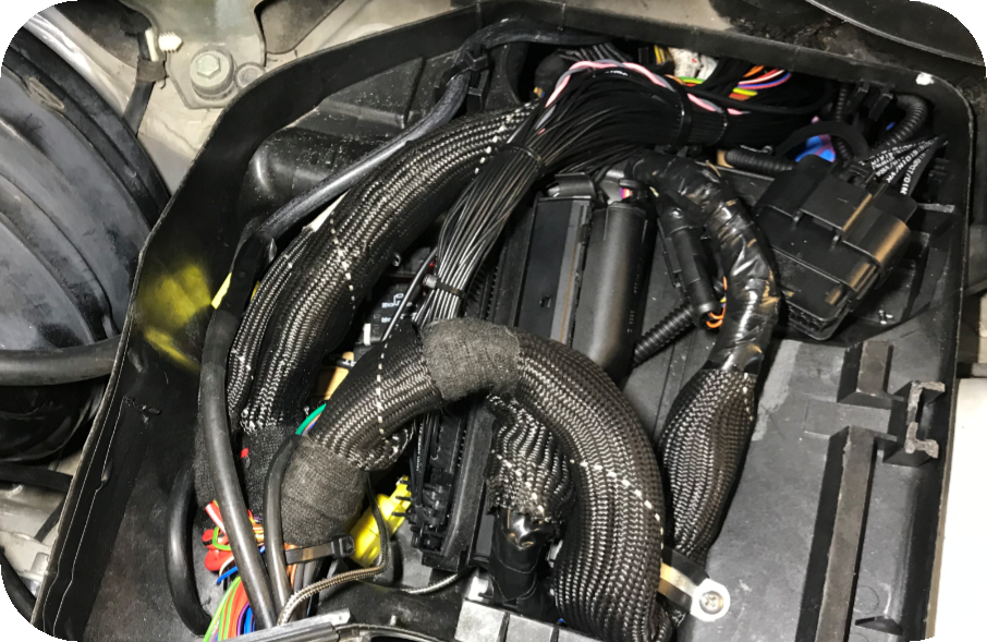
Preferable route all extra cables within stock rubber bushings.
8-pin extra connector (WBO)
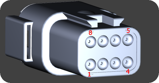
Seen from the wire side of the pre-wired connector.
Pin |
Description |
1 |
WBO: VREF |
2 |
WBO: VS |
3 |
WBO: Shield |
4 |
WBO: IP |
5 |
WBO: RCAL |
6 |
- |
7 |
WBO: +12V |
8 |
WBO: Heater- |
Note: If you vehicle is equipped with a stock LSU 4.2 sensor, do not connect a external here, see vehicle cover list above.
16-pin extra connector
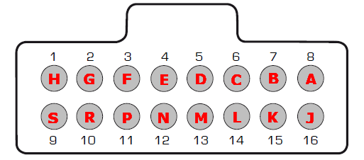
Note: Pinout is from the wire side of the pre-wired cable harness.
Pin |
Description |
Usage |
Note |
1 (H) |
+5V sensor supply |
|
|
2 (G) |
Sensor GND |
|
|
3 (F) |
TPS AIN |
TPS analog input can be used for external sensors, such as oil pressure, fuel pressure etc |
|
4 (E) |
AIN 4 |
|
|
5 (D) |
DIN/VR 4 |
|
|
6 (C) |
DIN/VR 5 |
|
|
7 (B) |
- |
- |
|
8 (A) |
GPO 7 / DIN 3 |
|
|
9 (S) |
|
|
|
10 (R) |
|
|
|
11 (P) |
|
||
12 (N) |
+12V |
Output at ignition on |
|
13 (M) |
Engine GND |
|
|
14 (L) |
AIN 1 |
||
15 (K) |
AIN 2 |
||
16 (J) |
AIN 3 |
See also
Example wirings of extra input and output