Vehicle cover list
Vehicle |
Engine code |
Year |
LSU sensor |
Note |
Mitsubishi EVO 4 |
4G63T |
1996 - 1998 |
External LSU needed |
|
Mitsubishi EVO 5 |
4G63T |
1998 - 1999 |
External LSU needed |
|
Mitsubishi EVO 6 |
4G63T |
1999 - 2001 |
External LSU needed |
|
Mitsubishi EVO 7 |
4G63T |
2001 - 2003 |
External LSU needed |
|
Mitsubishi EVO 8 |
4G63T |
2003 - 2005 |
External LSU needed |
Note: Manual transmission only!
Control options
The MaxxECU adapter for Mitsubishi EVO IV - VIII can be used with V1/RACE or PRO ECUs
EVO 4,5,6 |
EVO 7,8 |
MaxxECU IO |
V1/RACE/PRO |
Note |
AC clutch |
Fuel pump (main) |
GPO 3 |
Yes |
|
Fuel pump (stage 2) |
- |
GPO 5 |
Yes |
Lower the fuel pump capacity on EVO VIII... |
Tachometer |
Tachometer |
GPO 8 |
Yes |
|
Check engine light |
Check engine light |
GPO 2 |
Yes |
|
Idle stepper |
Idle stepper |
INJ 5,6,7,8 |
Yes |
|
Boost solenoid |
Boost solenoid |
GPO 4 |
Yes |
Uses stock solenoid |
Engine FANs (high + low) |
Engine fan (PWM) |
GPO 6 |
Yes |
|
Vehicle speed |
Vehicle speed |
DIN 1 |
Yes |
|
Fuel pump (stage 1) |
AC clutch + AC FAN |
GPO 1 |
Yes |
|
AC request |
AC request |
DIN 2 |
Yes |
|
- |
EVAP valve |
GPO 7 |
Yes |
Also connected to extra 16-pin connector |
- |
Clutch switch |
- |
|
|
- |
Intercooler sprayer |
- |
|
|
- |
Sec air system solenoid |
- |
|
|
- |
Evap vent solenoid |
- |
|
|
Idle position switch |
AYC/ACD signal |
- |
|
|
- |
EGR |
- |
|
|
Bluetooth (MDash) |
Bluetooth (MDash) |
- |
Yes |
|
Knock sensor(s) |
Knock sensor(s) |
- |
|
|
EGT option |
EGT option |
- |
Yes, direct |
|
Note: This plugin adapter uses only connector 1 on MaxxECU RACE/PRO units, for extra functionality, the second harness can be added to the RACE ECU.
The PRO ECU have in total of four ECU connectors which could be added for extra functionality: second harness, third harness and/or harness 4.
Run both engine fan and AC fan at the same time
Some high horsepower EVO VIII customers might want to activate engine fan and AC fan at the same time to cool down engine faster, you need to reroute
some cables in the harness.
Note: on EVO 7,8 MaxxECU GPO 1 (CMC 1: B4) is connected to AC clutch relay (pin 8) AND AC FAN HIGH (pin 32)
If you don't have AC, just simply cut the pin 8 wire and change the output function of GPO 1 in MTune to Engine Fan.
If you have AC (and inted to keep it), you need to move the AC FAN HIGH (pin 32) from MaxxECU CMC 1: B4 to MaxxECU CMC 1: B1 and activate that output as Engine Fan.
Note: Both fans will then be relay switched, aka PWM fan control will be lost of main fan.
This is just an example, of cource you can use any other available MaxxECU output to control the AC FAN.
Plugin adapter description
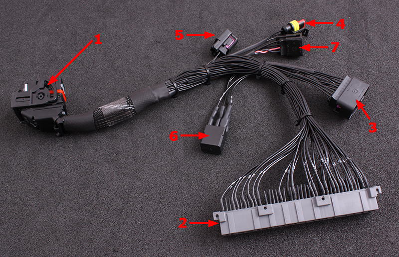
1 |
MaxxECU CMC 1 connector |
2 |
Vehicle harness adapter |
3 |
16-pin extra connector |
4 |
3-pin extra connector for ex. pressure sensor, analog input 4(AIN 4) |
5 |
2-pin extra connector for external intake temperature sensor (IAT). Not included |
6 |
Main ECC relay |
7 |
4-pin extra ODBII connector |
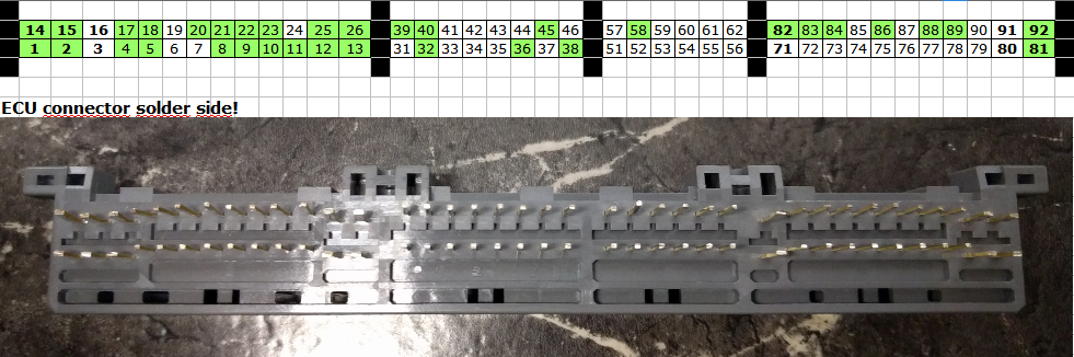
ECU location and installation
Stock ECU is located behind plastic guard on passenger side floor.
1.Remove the plastic guard where the ECU is located.
2.Disconnect battery from vehicle.
3.Remove and disconnect stock ECU from vehicle harness.
4.Install MaxxECU adapter harness.
5.Route the included MaxxECU MAP-sensor hose to the intake manifold and connect into the MaxxECU.
6.Route wide band lambda cables to exhaust system, install lambda sensor in exhaust and wire the lambda sensor as instructed below.
3-pin extra connector (0-5V analog input 4)
1 |
Sensor GND |
2 |
Analog input 4 (0-5v) |
3 |
+5V sensor supply |
see also, analog input.
16-pin extra connector
Note: Pinout is from the wire side of the pre-wired cable harness.
Pin |
Description |
Usage |
Note |
1 |
Wide band (VREF) |
|
|
2 |
Wide band (VS) |
|
|
3 |
Wide band (shield) |
|
|
4 |
Wide band (H-) |
|
|
5 |
|
|
|
6 |
- |
|
|
7 |
- |
|
|
8 |
GPO 7 / DIN 3 |
Parallel connected to stock EVAP solenoid, to use this, EVAP solenoid connector MUST be disconnected |
|
9 |
Wide band (IP) |
|
|
10 |
Wide band (RCAL) |
|
|
11 |
+12V |
Output |
|
12 |
+12V |
Output |
|
13 |
Engine GND |
|
|
14 |
AIN 3 |
||
15 |
AIN 1 |
||
16 |
AIN 2 |
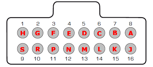
4-pin extra connector for OBDII functionality
A |
CAN H (grey wire) |
B |
CAN L (pink wire) |
C |
+12V |
D |
Engine GND |
See also, CAN OBDII.
3-pin extra connector (0-5V analog input 4)
1 |
Sensor GND |
2 |
Analog input 4 (0-5v) |
3 |
+5V sensor supply |
see also, analog input.
Internal wide band lambda (Bosch LSU 4.2) connection
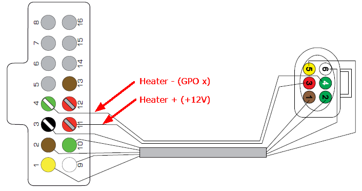
LSU 4.2 wiring with MaxxECU Plugin solutions.
Note: Seen from the wire side of the pre-wired connector.
PIN |
Function (LSU 4.2) |
1 |
VS |
2 |
RCAL |
3 |
+12V |
4 |
H- |
5 |
VREF |
6 |
IP |
See also external wide band lambda wiring.
Optional: Install external intake air temperature (IAT) sensor
Some vehicles are not equipped with an intake air temperature (IAT) sensor and MaxxECU plugin solutions do have the
option to add a sensor.
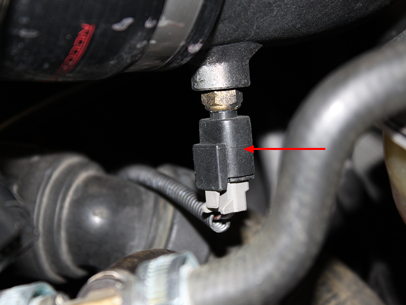
The intake air temperature (IAT) sensor should be mounted to sense fresh air flow going into the engine.
Depending on the intake manifold construction, the position of the temperature sensor is not given, but preferably mount
the sensor in the intake, or in the pipe before/after the throttle.
IAT wiring
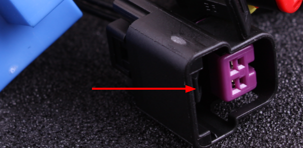
MaxxECU plugin solution are equipped with an optional 2-pin connector for optional IAT wiring.
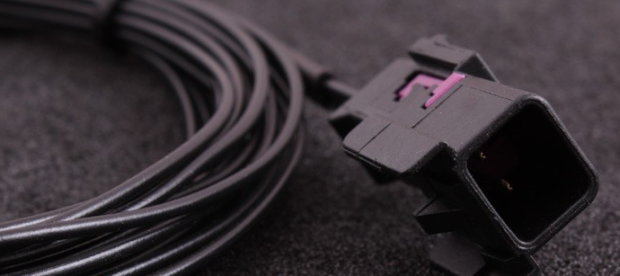
Mating connector and wires for external IAT sensor.
See also
Example wirings of extra input and output