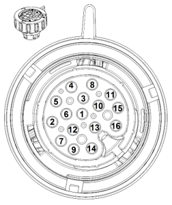
8HP GEN1 gearbox connector pinout, looking into the connectors terminal side.
Note: the 8HP TCU does not have a built-in terminator resistor.
8HP GEN1 gearbox connector pinout, looking into the connectors terminal side.
Dodge 8HP GEN1 connector pinout
Pin |
Description |
8HP usage |
Note |
1 |
|
|
|
2 |
|
|
|
3 |
|
|
|
4 |
|
|
|
5 |
CAN H |
CAN High |
|
6 |
CAN L |
CAN Low |
|
7 |
|||
8 |
|||
9 |
+12V |
Wakeup signal |
|
10 |
|||
11 |
|||
12 |
|||
13 |
+12V |
Main power supply |
|
14 |
GND |
Ground |
|
15 |
|||
16 |
Note: The power-up sequence is critical. The main power supply must be active continuously (or at least 10–15 s) before the wake-up signal is applied. If not, part of the TCU will fail to initialize and the paddles will not function in manual mode.
12-pin GT150 connector
Pin |
Description |
Usage |
A |
+12V (power supply), 15A fused |
Can be powered by a constant/powerhold relay |
B |
+12V (wakeup signal) |
Key_on |
C |
CAN H |
To MaxxECU CAN H |
D |
|
|
E |
|
|
F |
||
G |
GND |
To chassie/engine GND |
H |
||
J |
CAN L |
To MaxxECU CAN L |
K |
||
L |
||
M |
Note: The power-up sequence is critical. The main power supply must be active continuously (or at least 10–15 s) before the wake-up signal is applied. If not, part of the TCU will fail to initialize and the paddles will not function in manual mode.
Dodge Shifter connector
Pin |
Description |
Usage |
Note |
1 |
+12V |
Main power supply |
|
2 |
|
|
|
3 |
|
|
|
4 |
CAN H |
CAN High |
|
5 |
CAN L |
CAN Low |
|
6 |
|
||
7 |
|
|
|
8 |
|
|
|
9 |
|
||
10 |
GND |
Ground |
|
BMW F series shifter connector (10-pin)
Pin |
Description |
Usage |
Note |
1 |
|
|
|
2 |
|
|
|
3 |
CAN L |
CAN Low |
|
4 |
CAN H |
CAN High |
|
5 |
|
||
6 |
|
||
7 |
+12V (wakeup) |
Wakeup signal |
|
8 |
GND |
Ground |
|
9 |
|
|
|
10 |
+12V |
Main power supply |
|