MaxxECU CO2(compressed air) boost controller setup.
What you need
•A regulated air supply of 1.5x the required top can pressure is required. Ex: if 30psi (300Kpa) of top can pressure is needed then 45Psi of regulated air is required. (The 45psi may needs to be adjusted later, but this is a good start).
•Manifold pressure MUST be supplied to the bottom port of the external wastegate.
•User can have a very low waste gate spring (base spring) using this method. Use the spring that matches the lowest boost pressure you require.
•One 3 port solenoid is used to increase the pressure to the top of the waste gate. See below drawing.
•Another 3 port solenoid is used to decrease the waste gate pressure. See below drawing.
•A “Gauge” pressure sensor is required for measuring top can waste gate pressure. 0-75psi is recommended. “Gauge” pressure sensors always start at “0” where the other types will vary with atmospheric pressure.
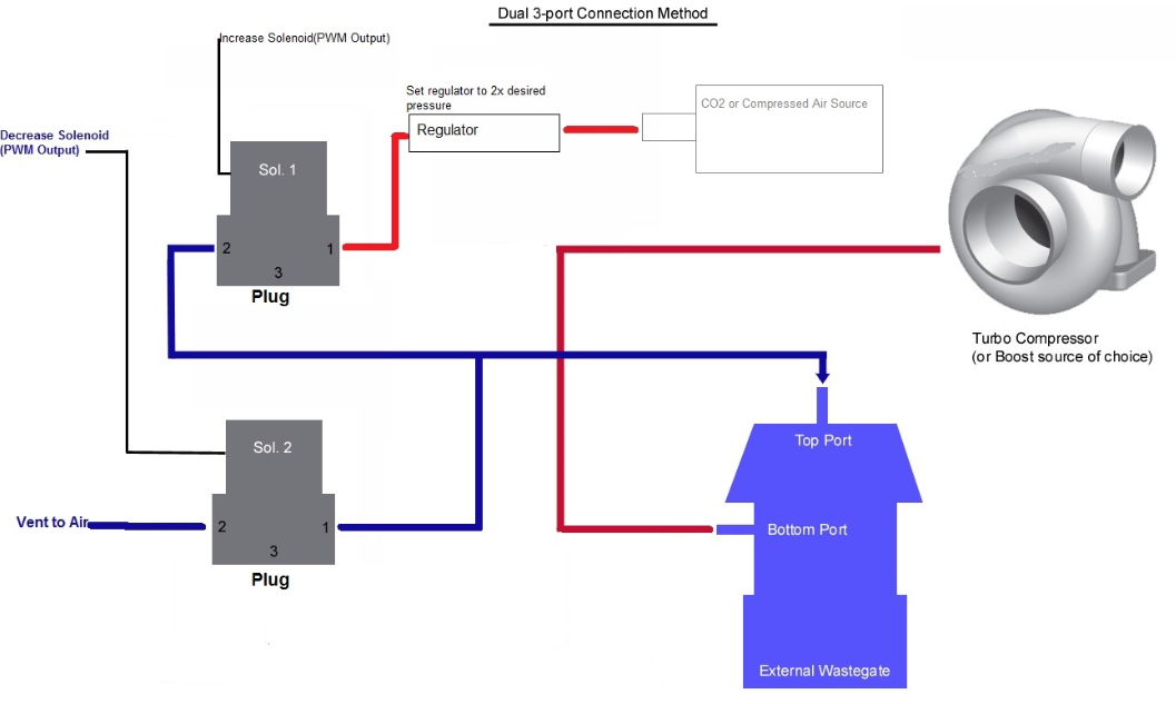
One solenoid (configured as Boost solenoid (closed loop) is used to increase the pressure to the top of the wastegate and the second solenoid (configured as boost solenoid (closed loop) decrease solenoid) is used to decrease the pressure.
How to configure

1. Configure outputs to have a Boost solenoid (closed loop and a boost solenoid (closed loop) decrease solenoid. In this example we use INJ 6 and 7.
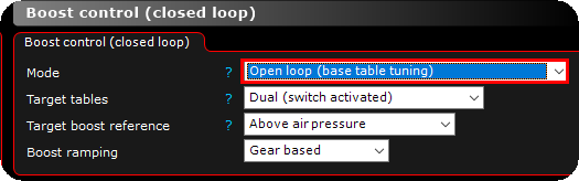
2. Initially set the Mode to open loop (base table tuning) in Outputs --> Boost control (closed loop).
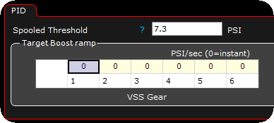
3. The target boost ramp setting allows the tuner to set a “ramp” rate for the target boost. A setting of “1” means the controller will increase the wastegate pressure 1psi per second until the next gear is selected.
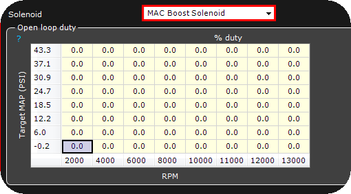
4. Select the type of solenoid to be used, custom values (20Hz and 5Ms is a good starting point) can also be entered of not using any of the preset solenoids that are available in the dropdown list.
Note: Make sure to add "0" in all cells here, otherwise this function will not work as a CO2 boost controller.
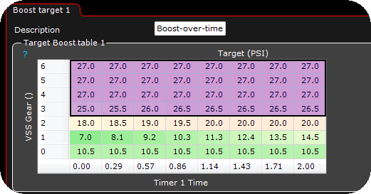
5. Populate the target boost table with your target wastegate pressure. In this example we use imperial values (metric values can also be used of cource). Axis can also be anything, ex Gear, RPM, TPS, Timers, G sensors or whatever.
Note: 0 in the above gear is Neutral position.
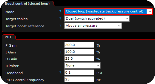
6. Next we must change the mode to closed loop (wastegate back pressure control). and do the necessary changes to suit your need.
In the above example we have given in two targets, which is switched by triggering the digital input function boost target switch (use table 2).
Boost control (closed loop)
Target boost reference
Tells the ECU the starting point of the pressure value.
•Above air pressure - Normally used when units are Imperial(US Standard).
•Above Absolute Vacuum - Used for Metric systems where “0” is the lowest value.
PID
P Gain
P stands for Proportional Gain. This value is the initial speed of attack for the controller. If the number is too high then the controller will over shoot the target. Too low and the controller will be slow to approach target.
I Gain
I stands for the integral gain. After you have set the “P” the “I” can be adjusted. The “I” is used to hold the target after it is reached. To high of an “I” value and the controller will pulse. To low and the controller will lower the pressure after it has been reached.
D Gain
D stands for derivative gain. You can leave this set to “0” for the CO2 boost controller.
see, PID control for more information.
Note: The above PID values should be a very good starting point for most setups.
Separate PID for decrease solenoid
The duty cycle needed to control the increase and decrease solenoids, can be different. The Increase solenoid lets pressure in and the decrease lets pressure out. These 2 different jobs can require different PID setting. Use this option to enable separate PID for the Decrease solenoid. Tune the PID with the Disabled option first. If you see the actual pressure not tracking the Actual target then try enabling this and tune the PID for the Decrease solenoid.
ILimiter
In some cases the “I”, or integral gain, will “wind up” and pulse out of control. This setting fixes that problem.
deadband
This is the minimum error the control needs to see before it starts the PID controller. If you set this to 0.1PSI, the PID loop will stop once the wastegate top can pressure is below 0.1PSI.
If your PID settings are incorrect and the dead band is too low, the controller will pulse. Increase this to ~1psi(7kpa) while adjusting the PID settings.
PID control frequency
How often the ECU samples the wastegate pressure value for correction. 100Hz means the ECU samples the Actual wastegate pressure and calculates the PID change. Too High can cause an unstable PID control. Start with 100Hz.
target boost ramp rate
This value sets the Ramp of the wastegate pressure. 0 is instant ramp, 50 means the wastegate pressure will increase at 50kPa/sec. Use this setting to help control power during launch.
solenoid
control enable
How the control is enabled.
Solenoid
The Solenoid used.
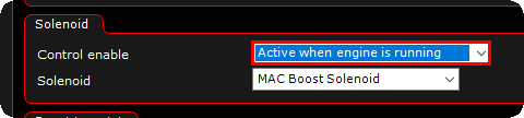
The control enable setting set to always active instead allows the tuner to test the boost controller when the engine is not running.
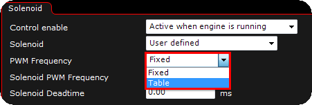
Optionally you can select a table for the PWM frequency insterad of a fixed value, which will open a table to enter different frequencies based on the boost pressure error.
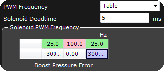
Here is a simple “User Defined” Frequency table based on the pressure error. In this table the MaxxECU will decrease the Solenoid frequency the larger the error gets.
The lower the frequency the more air the solenoid will flow per pulse. This means when the error is large the solenoid will flow more to correct the error quicker. As the error approaches “0” the frequency goes to 100Hz. This will lower the flow making the control much better at a low errors.

In the above image you can see a table for “Max duty”. This table will help the PID controller by telling it that there is a “MAX” duty for the system.
Be sure to log this before adjusting. You want to make sure the solenoid duty is going high and that is causing the problem. If so, you can lower the MAX Duty for the solenoid.
How to tune and adjust your settings using the built in logger
[not done yet]