MaxxECU supports the Volvo power steering found on the Volvo P1 platform.
Note: Before you proceed, make sure your hoses on the servo pump is pressed hydraulic hoses, regular hose clamps are not suitable for high pressure applications.
Support

Power steering module identification
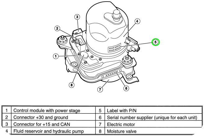
Control module, electric motor, hydraulic pump and fluid reservoir are all in one unit.
Wiring information
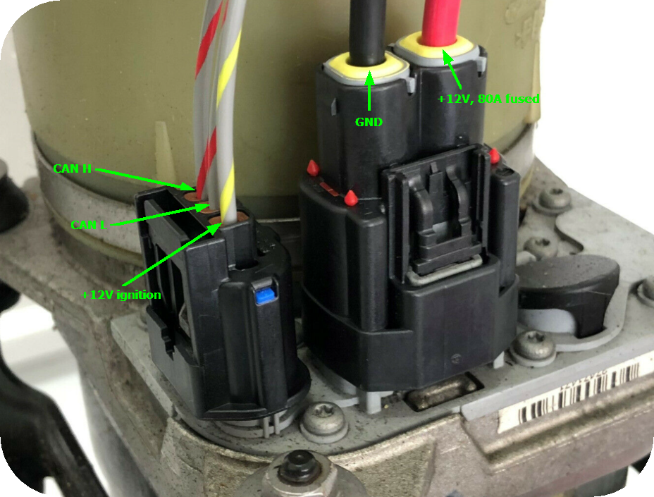
Power steering module wiring information. The power consumption can vary between 6 and 80A depending on the conditions, so a 80A fuse is mandatory.
Note: If using a PDM for all other electronics, please route the power steering outside the PDM system to use a separate fuse and relay for any kind of power steering (the flyback generated from a power steering can kill the most powerful flyback protection).
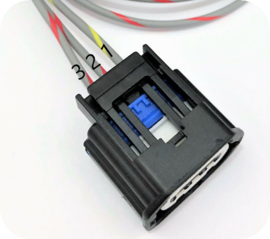
1: +12V ignition. 2: CAN L. 3: CAN H.
Software configuration
The +12V input on the 3-pin connector needs power for the pump to start up. We recommend to have this wired in so that the pump only starts after the engine has started.
In the below example use use a +12V GPO on a RACE in order to do this.
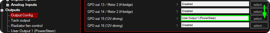
1. Selected an available User output function on any wired +12V output, in this example GPO 15.
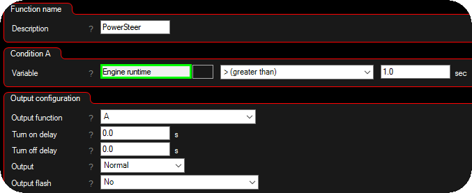
2. Configure the user output to output constant +12V when the engine is considered started, in this case when engine runtime is greater than 1 second.
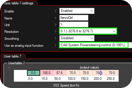
3. Create a usertable (Advanced --> User tables), make sure you set the 0.1 resolution, and the analog input function to CAN system powersteering control. The usertable now controls the pump speed with 0 to 100%, where 100% is the fastest. Any axis combination and also 4D is available on the user tables.

4. Enable the actual output protocol.
Note: If no pump is present on the bus, the MaxxECU will not transmit any CAN messages and no error code will be present. No EPS on the bus = no control.
If everything is wired correctly then you will notice that the pump has a soft start when 12+ is applied. If not the pump goes into a limp mode a the pump starts immediately.
How the Electronic Power Steering (EPS) module works
The power steering module (EPS) calculates the temperature in all power stages, if the temperature is too high (above 175°C), the power is limited. There is a temperature sensor (NTC) in the EPS which senses the temperature in the control module. High temperature above 110°C at the self test (startup) = the pump does not start. Above 120°C while driving = the pump is shut off.
Low temperature, the speed of the motor is reduced to limit the servo power. This is because the viscosity of the hydraulic fluid, and therefore pressure, increases at low temperatures.
The EPS module communicates with a number of other control modules via the CAN, CEM, BCM, ECM, SWM, which the MaxxECU simulates.
Connectors
2-pin main power connector: MaxxECU product id 2270.
Changelog
MTune 1.161: Increased the update rate of CAN message 0x2104136 from 50 ms to 10 ms for faster communication and improved response time.
Help and contribution
Henrik Gustafsson, Power Meet AB, Sweden.