Vehicle CAN data can be used in MaxxECU for trigger certain functions, or log data if CAN ID are known.
A CAN analyzer must be used to "sniff" vehicle CAN, if the CAN ID/data are not known, example of a good and simple CAN analyzer: www.cananalyser.co.uk/
For more information regarding CAN bus: wikipedia.org/wiki/CAN_bus
CAN input value
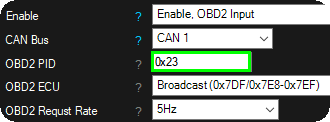
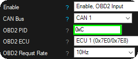
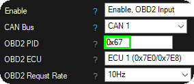
Enable
•disabled
•Enable, CAN message input - receive CAN messages, used as any analog class or bit mask to be used as a Digital inputs signal.
•Enable, obd2 input (mode 01) - Request ODB2 PID (mode 01) data directly into this CAN input system, received into any analog class or bit mask to be used as a Digital inputs signal.
•Enable, obd2 input (MODE 22) - Request ODB2 PID (mode 22) data directly into this CAN input system, received into any analog class or bit mask to be used as a Digital inputs signal.
CAN Bus
Specifies which CAN bus to use (more than one CAN bus is only available in MaxxECU PRO).
CAN message ID
Message ID (decimal value) to be used.
ODB2 PID
The OBD2 PID (mode 01) to request, see available PIDs, wikipedia OBD-II_PIDs.
ODB2 Extended PID
The OBD2 PID (mode 22) to request.
ODB2 ECU
The response ID the system is listening to.
ODB2 request rate
Specifies the requested update rate of the ODB2 PID requested value.

timeout
timeout
Whether to use a timeout on this particular message. If no message has been received within the timeout time, the value is zeroed out.
timeout time
Specifies the time to wait for a message. Specified in seconds.
match
Adds configurable pattern matching to CAN messages, allowing selective decoding of multiplexed or multi-frame data based on byte/bit masks.
match x
Enables conditional matching of CAN data. When used, parts of the message must (or must not) match a defined pattern before the signal is accepted. Useful for filtering specific values from multiplexed or multi-frame CAN messages.
byte offset
Defines which byte position in the CAN frame to check. Values above 100 are interpreted as a bit offset instead of a byte offset.
mask value
Defines the bitmask applied to the CAN data before comparison. Note: For 16-bit values, endianness is normalized prior to evaluation.
match value
Mask the Match value before comparing it. Used to ignore part of the match value.
0x00 or 0xFF / 0xFFFF = Mask not used (full value comparison).
0xF0 = Compare only the upper 4 bits; ignore the lower 4 bits..
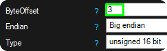
Data
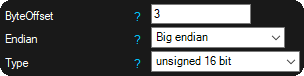
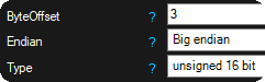
ByteOffset
Byte offset to use. Example: second byte, offset = 1.
Endian
Big-endian and little-endian are terms that describe the order in which a sequence of bytes are stored in computer memory.
•Big-endian is an order in which the "big end" (most significant value in the sequence) is stored first (at the lowest storage address).
•Little-endian is an order in which the "little end" (least significant value in the sequence) is stored first.
Type
8,16 or 32bit, also option for 4bit (high or low bits) capturing.
•Signed variables, such as signed integers will allow you to represent numbers both in the positive and negative ranges.
•Unsigned variables, such as unsigned integers, will only allow you to represent positive numbers.
mask
Mask operation applied before value conversion. Logical AND operation.
0xFFF to only use the first 12-bits of a 16-bit field for example.
Note: This option is onlu available on the first 12 CAN inputs.
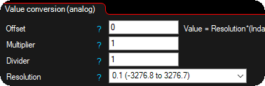
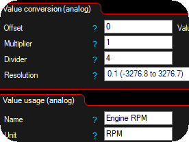
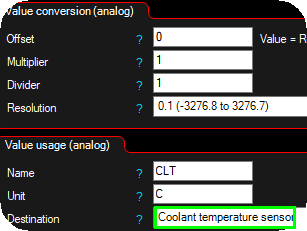
Value conversion (analog)
Value conversion mathematical formula
Value = 0.1*(Indata+Offset)*Multiplier/Divider
offset
Offset to use in the conversion formula.
Multiplier
Multiplier to use in the conversion formula.
Divider
Divider to use in the conversion formula.
Note: see below current value top check your final value to be used in MaxxECU.
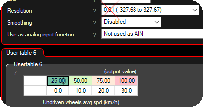
resolution
Specifies the sensor resolution on the selected input.
•1 (-32768 to +32767) - Values between -32768 and + 32767 can be used on the table (no decimals).
•0.1 (-3276.8 to +3276.7) - Values between -3276.8 and + 3276.7 can be used on the table (one decimal).
•0.01 (-327.68 to +327.67) - Values between -327.68 and + 327.67 can be used on the table (two decimals).
•0.001 (-32.768 to +32.767) - Values between -32.768 and + 32.767 can be used on the table (three decimals).
Warning/Note: When using a MaxxECU RealTime Data value in any in or output function, including comparing, the resolution (scaling) on all the values involved needs to use the same resolution values.
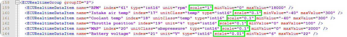
In short, always try to use the same resolution all over the sensors and tables. 0.1 is the most used resolution used across whole MaxxECU.
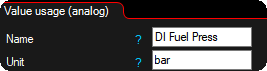
Value usage (analog)
name
Name of the converted value. Visible in MTune.
unit
Unit for the converted value. Visible in MTune.
destination
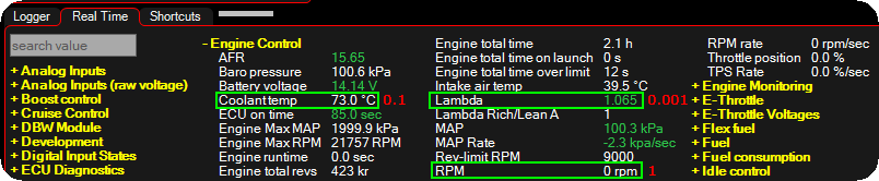
Value will be visible in RealTime Data --> User CAN inputs.
Can be used in MaxxECU as any other RealTime value for conditions or warning. For example it can be used to read GPS SPEED from CAN and use as a wheelspeed input.
Current value
The final value after all conversion, this value is to be used in MaxxECU.
Value usage (digital)
bit mask
Defines which bits in the byte you want to keep, and which bits you want to clear. MaxxECU here uses bitwise AND in order to extract a subset of the bits in the value.
To set the input, (value & bit mask) cant be "0" (>=1) to activate the MaxxECU digital input function below.
(Bit is either "0" or "1", and 8 bits grouped together makes 1 byte).
We can use the bit mask setting to "Query the status of a bit" in the byte value. In the below example, we have a certain byte which is changing from 149 to 157 when pressing the AC ON/OFF button.
Operation |
Bits |
Decimal value |
Value |
|
1 0 0 1 0 1 0 1 |
149 |
|
AND (&) |
0 0 0 0 1 0 0 0 |
8 |
Bit mask operation |
|
0 0 0 0 0 0 0 0 |
0 |
Output value |
|
|
|
|
|
1 0 0 1 1 1 0 1 |
157 |
Input value (AC ON) |
AND (&) |
0 0 0 0 1 0 0 0 |
8 |
Bit mask operation |
|
0 0 0 0 1 0 0 0 |
8 |
Output value |
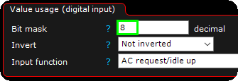
When we apply the above example settings in MTune to trigger the AC request/idle up function in MaxxECU, from the fourth bit in the byte value.
mode
•Momentary - if the matching bit is active, the controlled digital input function will be activated.
•inverted Momentary - If the matching bit is active, the digital input will be deactivated, and the other way around if the queried bit is not active.
•latching - If the matching bit is active, the controlled digital input will not be affected until a bit changes, then the digital input function will change state.
•latching, keep state at power off - If the matching bit is active, the controlled digital input will not be affected until a bit changes, then the digital input function will change state. The bit state will be remembered at power off and used at power on.
input function
Use the digital input value directly on a MaxxECU input function. <-- use with caution...
Old Examples (without the bit mask function)
Note: 0x430 is hexadecimal and it's the same as decimal value 1072.
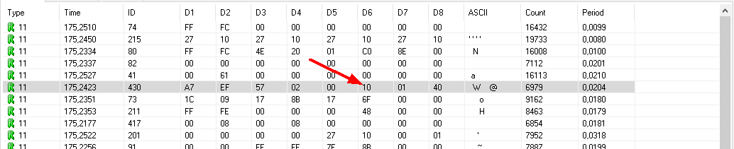
A display from a CAN analyzer on a Ford Mustang 2011, ID 0x430 (hexadecimal) is highlighted and in this example we pay attention
to the sixth byte (D6) which has default value of 0x10 (hexadecimal).
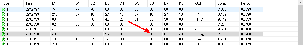
Same CAN analyzer output on this Ford Mustang, but right now the Traction/EPS button is pressed. ID 0x430 (hexadecimal) and D6
value was now changed to 0x90 (hexadecimal).
Conclusion: When press and hold the Traction button, CAN ID 0x430, D6 byte is changed from 0x10 to 0x90.
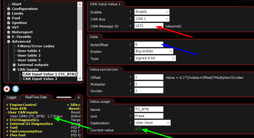
Red arrow: Enter the decimal value which we will use as input 0x430(hex) = 1072(dec).
Blue arrow: Since the data we are looking for is in the sixth byte (D6) we will enter a byte ofset of 5 (skip the bytes before and just pay attention to the D6).
Green arrows: Indicated the converted value from vehicle CAN when Traction button is untouched, which can be used in MaxxECU for controlling functions
using internal output or virtual inputs.
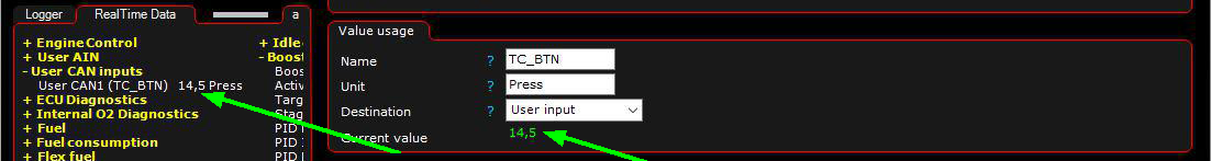
Green arrows: Indicates the converted value from vehicle CAN when Traction button is pressed.
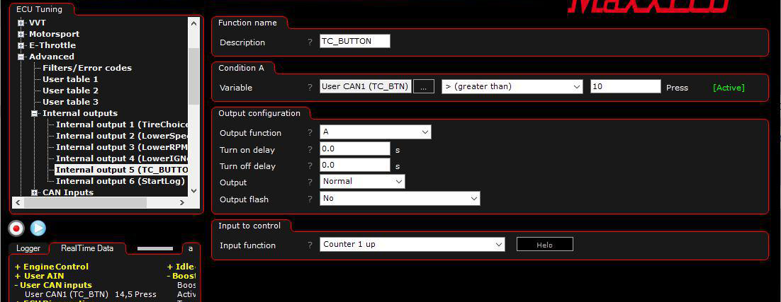
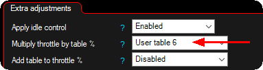
In the above example the Ford Mustang Traction button only change value on the CAN when pressed, therefore we will use an internal output to take use of a
counter, which then later is triggering the Disable traction input function.
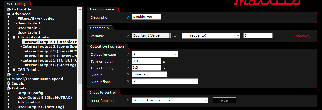
Another Internal output is used to disable the Traction control feature (which is active all the time in the Traction control settings). Pay attention to the Inverted output since we
trigger the internal function Disable Traction control.
Note: This was just a simple example of what can be made using the User CAN input function, a lot of more advanced functions can be made.