Lambda sensor
lambda sensors
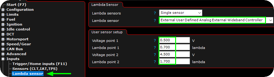
Specifies number of available lambda sensors in the system.
•Single sensor - Mostly used on straight engines.
•2 sensors.
Lambda sensor X
Specifies the lambda sensor to be used on this lambda channel.
•None - No lambda sensor enabled in the system, a lot of features is not functioning without a wide band sensor, it is very advice able to have a sensor connected to the MaxxECU.
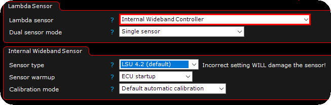
•Internal wideband controller - A wideband sensor is wired to the MaxxECU.
•MaxxECU CAN Lambda module, ID x - Support for the MaxxECU CAN WBO sensor, up to 8pcs extra on a single MaxxECU installation, see CAN Lambda Module Setup.
•narrowband sensor - Support for narrowband sensor (do not use this type of sensor...)
•External user defined analog external wideband controller - Brings up an calibration page to scale your own 0-5V lambda controller.
•External wideband controller (AEM UEGO) - https://www.aemelectronics.com/products/wideband-uego-air-fuel-controllers/digital-wideband-uego-afr-gauge
•External wideband controller (AEM X-series (30-0300)) - https://www.aemelectronics.com/?q=products/gauges/digital-gauges/x-series-wideband-uego-afr-sensor-controller-gauge
•External wideband controller (afm1000 std) - http://www.ecm-co.com/product.asp?a1000
•External wideband controller (afm1000 B-version) - http://www.ecm-co.com/product.asp?a1000
•External wideband controller (afm1000 C-version) - http://www.ecm-co.com/product.asp?a1000
•External wideband controller (afm1000 D-version) - http://www.ecm-co.com/product.asp?a1000
•External wideband controller (haltech methanol) - https://www.tmzperformance.com/shop/haltech-methanol-wideband-controller-w-ext-harness-ntk-sensor-weld-bung-ht-010720/
•External wideband controller (Innovate) - https://www.innovatemotorsports.com/products/lc1.php
•External wideband controller (PLX) - https://www.plxdevices.com/PLX-Wideband-O2-Air-Fuel-Ratio-Sensor-Modules-Gauges-s/125.htm
•External wideband controller (techedge) - https://wbo2.com
•External wideband controller (zeitronix) - http://www.zeitronix.com/Products/zt2/zt2.shtml
•External CAN wideband controller (User defined) - Customize your own lambda CAN input, using the User CAN Input function, and set the destination to Lambda sensor bank X.
•External CAN wideband controller (AEM X-series) - https://www.aemelectronics.com/?q=products/gauges/digital-gauges/x-series-wideband-uego-afr-sensor-controller-gauge, (CH1 = 0x180, CH2 = 0x181).
•External CAN wideband controller (exqbe dual wbo controller/CAN) - Discontinued product.
•External CAN wideband controller (Haltech 1 Channel) - HT-159978 1ch Haltech NTK.
•External CAN wideband controller (Haltech 2 channel) - HT-159988 2ch Haltech NTK.
•External CAN wideband controller (HV Electronics) - https://hv-electronics.myshopify.com/collections/hv-lambda-can-devices, (CH1 = 0x29F, CH2 = 0x2A0).
•External CAN wideband controller (Link CAN LAMBDA) - https://dealers.linkecu.com/canlambda. Mod 1 = 951 (0x3B7), Mod 2 = 952 (0x3B8), Mod 3 = 953 (0x3B9), Mod 4 = 954 (0x3BA). Does not send the optional control message 958 to the lambda modules. If you want this, send it with CAN Outputs.
•External CAN wideband controller (Motec LTC/LTCD) - https://www.motec.com.au/ltcd/ltcdoverview/, CH1 = 0x460, CH2 = 0x461, CH3 = 0x462, CH4 = 0x463).
•External CAN wideband controller (Motec PLM) - https://www.motec.com.au/products/PLM?catId=10 (CH1).
•External CAN wideband controller (ECU master) - https://www.ecumaster.com/products/lambda-to-can/ (CH1 = 0x664, CH2 = 0x666).
Note: MOTEC LTC/LTCD CAN LAMBDA: Motec LTC/LTCD internal diagnostics works with a delay so the error codes will not go away immediately, but 60s after fault is fixed. The Motec Fault bits are displayed in the RT-values "External sensor status 1/2"
sensor warmup
Specifies when the lambda heater and error detection will be activated.
•ECU startup - Started right after ECU is started (fastest option to get accurate lambda readings fast (10-15seconds)).
•Engine startup - Wide band sensor heating is started during cranking (mostly used in some Plugin solution where the LSU is powered from an external source like OEM fuel pump relay).
•Delayed startup - Specifies (seconds after engine is considered started) when the sensor warmup (and error detection) is started using a table.
sensor shutdown
Specifies how long after engine shutdown the lambda control should be active, 120 seconds after engine stops (default) or to keep sensor on when engine stops.
User sensor setup
Only available when the above lambda sensor = External user defined analog external wideband controller.
Voltage point 1
Specifies the lowest voltage point from the controllers output signal.
lambda point 1
Specifies the lambda value at the lowest voltage point.
Voltage point 2
Specifies the highest voltage point from the controllers output signal.
lambda point 2
Specifies the lambda value at the highest voltage point.
dual bank cylinder assignment
cylinder x 02 sensor
Specifies which sensor is mounted on which cylinder side. Bank A is always on the cylinder 1 side.
internal wideband sensor
sensor type
•LSU 4.2 - default and recommended sensor.
•LSU 4.9 - Not as sustainable as the LSU 4.2 sensor.
calibration mode
•default automatic calibration - MaxxECU reads the built-in resistor from factory to be used as calibration data.
•manual free air calibration - Manual way of calibrating the connected sensor (s), if you for some reason (like using an old and worn sensor) want to manually calibrate the sensor (s), see below.
free air calibration
Used to calibrate lambda sensor. Normally not used. MaxxECU will calibrate sensor automatically (when default automatic calibration option above is used), but this can be used to calibrate and old and worn sensor.
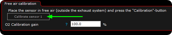
Make sure the wide band sensor has not been exposed for exhaust gases the closest hour, have the sensor OUTSIDE of the exhaust and press the calibrate sensor button for the relevant sensor.
sensor calibration
calibration mode
•Legacy calibration - The default calibration used by all MaxxECUs up until 2021-06..
•new calibration (2021) - The lambda sensor calibration curve has been adjusted to be more accurate over a wider area of operation. This mode is used for new tunes. Can be used with both old and new MaxxECUs.
Note: It's normally not recommended to change this after tuning an engine as this can make it run a tiny bit richer or leaner in some spots.
Broken sensor lean error
Detects conditions where the lambda sensor (internal or external) reads too lean.
If the sensor reads leaner than the threshold for longer than the set time when the engine is running, an error code is set and the lambda control is disabled.
lean sensor error
Enable/disable the broken sensor detection function.
Lean threshold
Specifies the leanest lambda value considered to be a valid lambda for the running engine.
Error delay
Specifies the delay (in seconds) to wait before throwing the broken sensor lean error, 112 - Lambda sensor malfunction. The signal is too lean.
Pressure correction
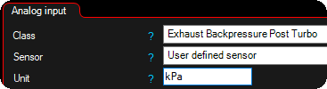
To be able to use this, a pressure sensor before or after the turbo must be installed.
If the lambda is mounted after the turbo in exhaust system, you must select the Exhaust backpressure post Turbo analog input.
calibration mode.
•No pressure correction - No pressure compensation is made.
•user set pressure correction - Specifies if a back-pressure compensation should be done on the measured lambda value. Requires a back-pressure sensor mounted.
sensor x correction.
Specifies if this sensor should be incorporated in the pressure compensation table.
•none - Exclude this sensor from the pressure compensation.
•correction table 1 - Include this sensor into the pressure compensation.
1. Wire the required back pressure sensor, which is needed to perform lambda pressure compensation.
2. Download the "load in" tunefile (LSU_xxx_pressure_correction.zip) from our website (downloads) and unpack to your desktop.
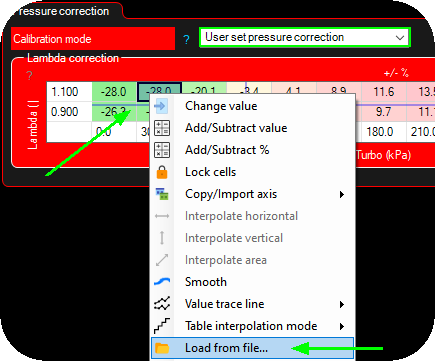
3. Enable the calibration mode, right click on the table and "load from file" and select the file to load into the tables.
Note: The lambda correction table can have ANY axis sources, it does not do anything magically in the background, it just compensate according to the table values.
Examples
Internal wideband controller with an LSU 4.2 sensor
Note: Requires an wideband sensor wired to MaxxECU.

1. Activate the GPO 8 as a internal lambda sensor heater (sensor 1).
2. Activate the lambda sensor as internal wideband controller.
External wide band controller wired to AIN 3 (0-5V)
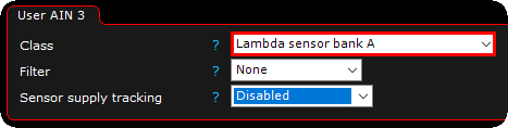
1. Inputs --> AIN (0-5V), select lambda sensor bank A on the relevant analog input (AIN) 0-5V channel your external wide band controller is wired to.
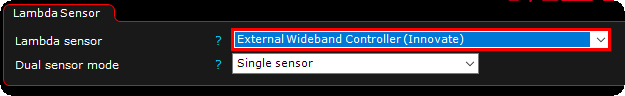
2. Inputs --> lambda sensor, select the external controller wired to the MaxxECU analog input. In the above example an Innovate LC-1 controller is used.
Dual wide band sensors wired to a MaxxECU PRO
Note: Requires two wideband sensors wired to MaxxECU.

1. Activate the wired lambda heater outputs, as the internal lambda heaters (internal lambda sensor heater (sensor 1/2)).
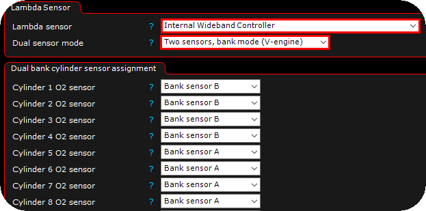
2. Enable the internal wideband controller, and the dual sensor mode as two sensors, bank mode (V-engine). Also set the sensor assignment to suit your engine.
External wide band controller wired to AIN 3 (0-5V) not found in the list of supported controllers
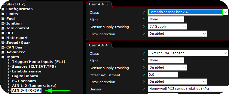
1. Inputs --> AIN (0-5V), select lambda sensor bank A on the relevant analog input (AIN) 0-5V channel your external wide band controller is wired to.
2. Inputs --> lambda sensor, select external user defined analog external wideband controller from the list, set voltage/lambda points according to your controllers data.