VVT is a very advanced function to control CAMs with advanced PID control, do not try this if you are not sure what your are doing.
For this setting page to be visible, please activate an output as VVT intake/exhaust cam solenoid.
VVT control
VVT control
Enable or disable VVT control of the selected CAM.
PWM frequency
The frequency used on the solenoid(s). Try to find the OEM frequency for your engine or find a frequency that results in a stable cam position and fast response.
The use of external flyback diodes are very important for some setups.
Solenoid pulse test
•Used to test direction of solenoid(s)
•Used to get min/max PWM duty.
•Used to get max controllable angle.
Test mode
Enable or disable the output solenoid duty test function.
Test mode duty
The duty to output, using the above PWM frequency.
-100 = fully retard solenoid. 0 = off. 100 = fully advance solenoid.
Test length
The amount of time to test the solenoid with the above specified duty.
Test
Press this button to activate the test duty on the solenoid specified with the above test length.
Regulator settings
Min PWM duty
Minimum PWM duty to be used on this CAM.
For dual solenoid systems (VANOS) this should be negative.
For single solenoids this is usually 0%, or the % where the solenoid begins to affect the cam.
Max PWM duty
Maximum PWM duty to be used on this CAM.
Usually 100%. Can be used to limit the force applied to the actuator.
Min controllable angle
Minimum angle of the CAM. Usually 0. Some systems don't like hitting the mechanical end, use a rather low value to prevent this from happening.
Max controllable angle
Maximum angle of the cam in most advance position.
Set this to a few degrees from the mechanical limit. Forcing the actuator against the limit can cause damage in long term usage.
P gain
Proportional value.
I gain
Integral value.
D gain
Derivative value.
see also, PID control explanation.
Examples
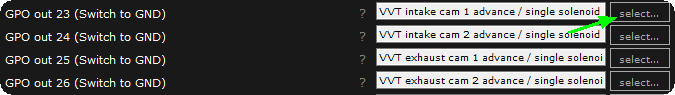
To make this control page to be visible in MTune, you must activate an output as a VVT intake/exhaust cam solenoid.
The VVT system in MaxxECU controls different types of variable-adjustable cams, called differently by car manufacturers (ex VANOS, VVTi, VTEC), but in MaxxECU we just simply call it VVT. Up to 4 cams can be individually controlled in MaxxECU.
VVT is a highly advanced feature that should only be set by users who fully understand how the engine's VVT system works and how to set a PID-control.
CAM control with on/off state (2 different fixed positions) shall not be used with this this VVT control system. See User output.
Note: Make sure that all valves operates freely in all modes of your engine, serious damage may occur in the event of incorrect settings of VVT control parameters.
Cam position (required for VVT control)
The actual CAM position in relation to the crankshaft, measured by a pulse sensor. Each individual CAM intended to be controlled, must have it's own CAM sensor.
Usually, one of the CAMs uses the same sensor as the HOME trigger system and must be connected to the HOME/CAM input wire on the MaxxECU.
Position 0 in MaxxECU is the unaffected CAM position (normally fully retarded).
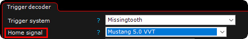
Important note: Most of our VVTi implementations do require the HOME SIGNAL to be used into the system, if you experience that sensor position on the cams might shift 360 degrees between start ups, most likely in this case is a missing home signal in the trigger system which is needed to keep track of engine phase.
Activating a CAM position sensor (using a shared sensor on HOME input)
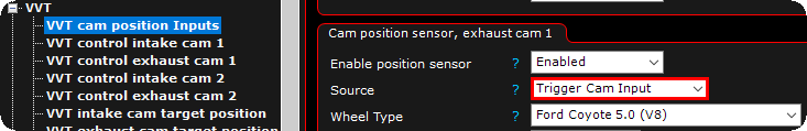
Typical settings for VVT cam position inputs when the source sensor is shared with the trigger system.
Note: The VVT position input is just sharing the signal, the actual trigger system must be correctly configured both in trigger and VVT settings.
If two or more CAMs are about to being controlled, position sensors must be connected to available Digital/VR inputs.
Activating a secondary CAM position sensor
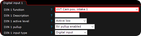
In the above example we have activated a CAM position sensor (for intake 1) on the Digital input channel 1.
Before moving on. Make sure all cam control solenoids are switched off and the engine can not start. Run the engine on the starter engine without spark plug and check the real-time values for the matched positions, such as "Intake cam 1 position".
Make sure you have a stable VVT position for the intended CAM.
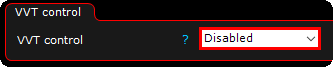
1. Make sure the control is disabled.
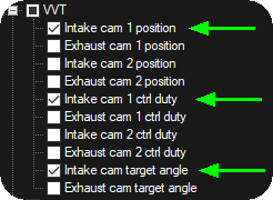
2. Right click on the live-logger, select channels and add the relevant ones, in the above example we intend to control the intake cam on the Coyote 5.0 engine with in total of 4 VVTi solenoids.
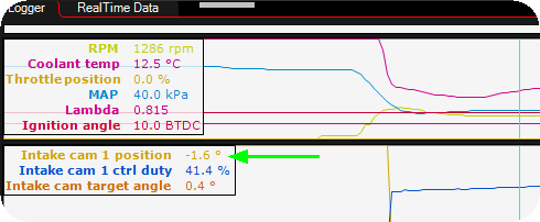
3. Crank the engine with fuel and ignition disabled or start the engine if you are sure what you are doing, check the relevant cam position value. The value should be quite stable, if the value jumps more than 5-10 degrees, something is wrong.
Note: If you do not have a stable position here, and it moves more than a few degrees, there is something wrong with the supported VVTi trigger pattern. Use the built-in Diagnostic tool --> Trigger logger. (compare your trigger output with our database of implementations).
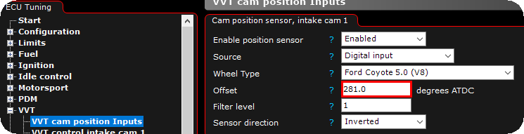
4. We assume you know which trigger pattern your engines has and selected the correct one. Adjust the offset value so that the position value in the logger is somewhere around 0 degrees when the control is deactivated. Values between -360 and 360 is preferred.
Note: Make sure the VVT control option is disabled as described above, and of cource the engine must be turning to verify the adjustments.
There are two types of when the most common is one solenoid per CAM (low PWM duty moves the CAM in one direction and high PWM duty in the other direction). The other type is using two solenoids per CAM, one for each direction.
Using the solenoid test and try to move the CAM
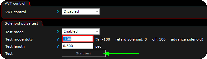
1. Activate the solenoid pulse test feature. Press the Start test button while checking the live-logger if something is happening.
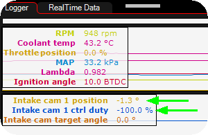
2. During the above solenoid pulse test, check the RealTime Data values for the relevant CAM position and make sure the CAM is moving.
Note: with a dual solenoid setup on each cam, and the CAM is not moving while doing a -100 retard solenoid test, please try to shift the outputs in output config, the setting sensor direction will also affect what you see here during movement.
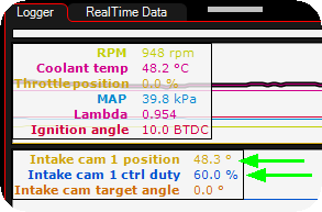
3. In the above example we use the solenoid pulse test with a positive value (+60% duty) and we can clearly see that the cam has moved to a 48.3 degree position (and the engine most likely run bad at this moment). This solenoid pulse test must also be used to find the Min and Max PWM duty below.
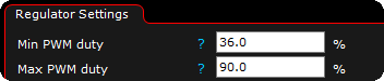
4. In this example, we found that around 50% duty, the cam started to make a movement, therefore we put the Min PWM duty to 36 (just a random example), and the Max duty to 90. Smaller control range = better and faster PID-control.
Note: in most cases a Min duty of 0 (or -100 depending on your setup) and a Max duty of 100% will be fine, but to fine tune, you can use this option.

5. The Min and Max controllable angle must also be set, this is also determined by using the above solenoid pulse test feature. This is needed for the MaxxECU to know in which range we actually can control the relevant CAM.
Note: Adjust the Min and Max angles to prevent the cam from hitting the mechanical stops.
Adding the control option and adjust PID
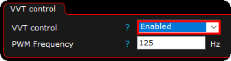
1. Input the correct PWM frequency for the relevant CAM solenoid and enable the VVT control.
Note: if PWM frequency is unknown for your solenoid, 125Hz is a good starting point, but you need to test different frequencies to make sure the best control options.
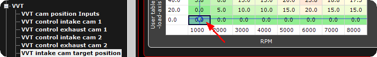
2. When the control is activated, the target position is used to move the CAM to the target, at idle, do a small adjustments here (like move it +10 degrees) and watch the output in the live-logger.
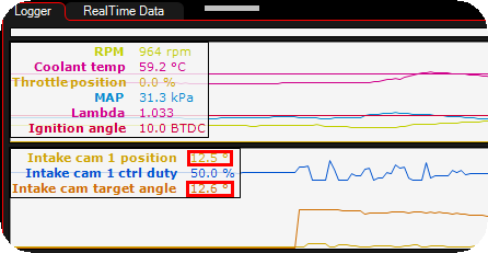
3. In this example, we commanded a 12.6degree CAM position and got 12.5, and you can clearly see the control duty required to move the CAM (blue line) and here we need to adjust the PID control to move the CAM a little smoother.
Note: Also remember that the oil temperature may affect the control options, so a good PID control at normal oil temperature may not work in cold conditions.