Support for GM 4L60E/4L65E and 4L80E/4L85E auto transmissions.
Wiring to make this transmisison work:
Inputs
•Speedsensor drive shaft RPM, VR-sensor.
•Speedsensor input shaft RPM, VR-sensor, optional to calculate transmission slip.
•Auto transmission gear selector A.
•Auto transmission gear selector B.
•Auto transmission gear selector C.
•Linepressure sensor on analog input, recommended. The OEM 4L80E does not include a linepressure sensor. Installing one allows MaxxECU to monitor actual line pressure and simplifies setup and diagnostics.
•Brake pedal/stop light active.
Note: Digital inputs are recommended whenever available, as they already include internal pull-up resistors suitable for switch-to-ground circuits. On GM 4L60E/4L80E transmissions, the OEM range switch cannot distinguish between Park and Neutral using only the A/B/C selector signals. Both positions share the same bit pattern. If a dedicated Park signal is required, use an additional switch and ECU input.
Outputs
•Transmission, shift solenoid A.
•Transmission, shift solenoid B.
•Transmission, line pressure solenoid.
•Transmission, 4L60E 3-2 acc solenoid, only on 4L60.
•Transmission, TCC/lockup solenoid.
Wirings
4L60E pin |
Description |
Suggested MaxxECU connection |
A |
Solenoid A |
GPO x |
B |
Solenoid B |
GPO x |
C |
Pressure control solenoid High |
+12V |
D |
Pressure control switched GND |
GPO x |
E |
+12V |
+12V |
L |
Temp sensor |
AIN x |
M |
Sensor GND |
Sensor GND |
N |
Pressure switch A |
DIN x |
P |
Pressure switch C |
DIN x |
R |
Pressure switch B |
DIN x |
S |
3-2 solenoid |
GPO x |
T |
TCC lockup |
GPO x |
4L80E pin |
Description |
Suggested MaxxECU connection |
A |
Solenoid A |
GPO x |
B |
Solenoid B |
GPO x |
C |
Pressure control solenoid High |
+12V |
D |
Pressure control switched GND |
GPO x |
E |
+12V |
+12V |
L |
Temp sensor |
AIN x |
M |
Sensor GND |
Sensor GND |
N |
Pressure switch A |
DIN x |
P |
Pressure switch C |
DIN x |
R |
Pressure switch B |
DIN x |
S |
TCC lockup |
GPO x |
4L80 pinout
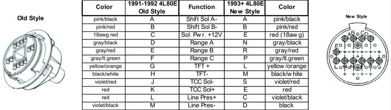
Pin assignments shown are the OEM transmission connector. Depending on the vehicle harness, wire colors may vary. Always verify the transmission connector pinout before wiring.
4L60 pinout
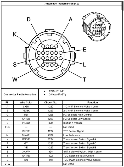
Pin assignments shown are the OEM transmission connector. Depending on the vehicle harness, wire colors may vary. Always verify the transmission connector pinout before wiring.
Troubleshooting
Just four bullet points:
If the gear selector does not follow the shifter position:
Verify each selector input has a pull-up resistor.
Verify the transmission range switch grounds each selector correctly.
Verify Sensor GND is connected.
Observe the A/B/C inputs in MTune while moving the shifter.