What are Pulse Inputs?
Universal configurable inputs for Crank, Cam, VVT, Flex Fuel, Turbo and Wheel Speed sensors. They replace the fixed-function inputs from MaxxECU GEN1.
Key features:
•All pulse inputs accept digital(Hall) or VR signals.
•Pulse 1 and 2 have selectable supply voltage (5V or 12V) for Hall effect sensors - ideal for crank and cam.
•Can be configured as standard digital inputs with selectable pull-up resistors.
Why it matters:
More flexibility in your wiring. No more "I've run out of speed sensor inputs" or needing adapters because your sensor needs 12V instead of 5V.
pulse settings
Description
Specifies a custom name for the input to clearly identify the connected device or function.
Function
Defines which digital input function is activated when the input becomes active.
Active level
Defines whether the function is triggered on a rising edge (low to high) or falling edge (high to low).
input settings
Input type
Defines how the ECU interprets the electrical signal on the selected input. The setting must match the connected sensor type, as it determines the trigger thresholds and signal processing method.
•Digital input - Uses a square wave logic signal and triggers on defined high/low voltage levels, see below threshold voltage.
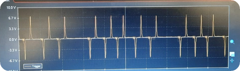
•VR input, zero crossing trigger - Triggers when the VR signal crosses zero volts. Requires a -0.16 to 0.16 -> 0,12 / 0.24V peak/peak signal. Used for 99% of all VR-sensors
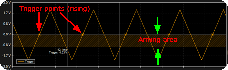
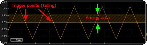
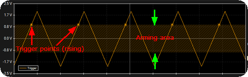
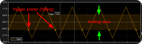
•VR input, level trigger (bipolar) - Triggers on defined positive and negative voltage levels when zero-crossing is slow, wavy or inconsistent.
Note: Max 25kHz and Max +/-200V.

Pullup resistor
Selects whether to enable the internal 1.0 kOhm pullup resistor to +5V on the input. When enabled, the input is triggered by grounding it. If disabled, a +5V or +12V signal must be applied to activate the input.
•no pullup resistor - No internal pullup connected.
•5v pullup enabled - 1.0 kOhm pullup connected to regulated +5V.
Note: Only available for digital inputs and not supported on all ECUs.
negative input
Selectable negative input configuration for Digital or VR signals. Supports internally grounded mode for normal installations, or floating mode for piggyback applications to avoid disturbing OEM signals.
•grounded - Internally grounded input. Recommended for most installations.
•floating - High-impedance floating input. Used when grounding the a piggybacked sensor sensors ground would interfer when OEM ECUs (ABS and OEM VR-sensors for example).
Note: Only avaible on MaxxECU GEN2 Pulse 1/2.
supply voltage
MaxxECU GEN2 PULSE 1/2 provides a selectable sensor supply on the pink wire in the shielded cable assembly.
•supply voltage off - No voltage output on the pink wire.
•5v supply enabled - Regulated +5V output on pink wire.
•12V supply enabled - +12V output on pink wire.
input thresholds
threshold voltage
Defines the digital input trigger levels, using default 3.5V and 2.0V thresholds for square wave signals or allowing custom rising and falling edge voltage thresholds for precise signal tuning.
•default (3.5/2.0V) - Uses a square wave logic signal and triggers on defined high/low voltage levels.
•Custom settings: Rising edge threshold - Defines the voltage threshold to use for the rising voltage. Must be larger than the falling threshold.
•Custom settings: Falling edge threshold - Defines the voltage threshold to use for the falling voltage.
Note: Only when input type is set to digital input.
threshold voltage
Defines the trigger voltage method, either via manual table-based settings or automatic signal tracking.
•manual voltage setting - Uses a user-defined table to set voltage thresholds.
•Automatic voltage tracking - Automatically adjusts trigger thresholds based on the input signal. Uses a threshold voltage of 17% of the peak value when the engine is not running, and 33% of the peak value when the engine is running.
Note: Only when input type is set to VR.
Digital inputs available in MaxxECU
•Advanced warning system, enable
•Advanced Warning System, Enable Cut
•After launch power limit disable
•Auto transmission gear selector
•Auto transmission lockup enable
•Auto transmission manual mode switch
•Auto transmission, enable WOT RPM shift
•Auto transmission, switch to 2nd shift table
•BMW MS 43 Steering Wheel Buttons
•Brake pedal/stop light active
•Edge-triggered pulse output X trigger input
•Electric waterpump override input
•E-Throttle Volvo backup pedal position (PWM)
•E-Throttle Volvo main and backup pedal position (PWM)
•Extra fuel table X table activation switch
•Extra ignition table X table activation switch
•Extra fuel/ign table activation switch (all)
•FAN + Electric waterpump override input
•Fuel adaptation, enable adaptation
•Hella coolant pressure and temperature sensor
•Hella oil pressure and temperature sensor
•Hella User pressure and temperature sensor
•Launch control switch, enable stage
•Logging, reset and start new file
•Power management system disable
•Power management system enable
•Rolling launch control switch
•RPM limit, use secondary limit RPM
•RPM limit, use secondary mode
•Speedsensor transmission input shaft RPM
•Speedsensor wheelspeed front/rear right/left
•Transmission Clutchkick/burnout mode (8HP)
•Transmission Converter Slip Request
•Trigger, HOME+CAM dual sensor, cam sensor
•Tripmeter, use Tripmeter 2/ fuel used 2
•Vehicle speed sensor VSS (simple)
•Virtual fuel tank reset level
•Water/Methanol injection, enable
•Water/Methanol Injection, low-level sensor