Pdm general settings
5V output activation
How the activation of the PDM +5V power supply output is enabled.
•Always on - +5V output on the PDM will always be active.
•ECU turn on - Will only output +5V when the ECU is turned on (when the PDM output ECU supply is active).
Automatic fault reset
Option to automatically restore tripped outputs, reset error codes and restore retry counters when turning on the ECU.
•Disabled - Tripped outputs can only be reset by the Reset pdm faults digital input, via MTune or by power cycling the PDM.
•clear faults when ECU is turned on - Tripped outputs will be reset when the ignition switch is turned on. If the short circuit/overload situation remains the faulty outputs will trip again.
Examples
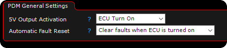
The above example will clear all stored PDM error codes and tripped outputs will be reset, also the PDM +5V output is active when the PDM is turned on and the PDM
Force one output to ECU supply
As a safety feature, when enabled (default) if you mess up and no output is assigned as the ECU supply, on next PDM boot, it will automatically revert OUT 1 to ECU Supply.
•Enabled - Safety on, if you mess up, PDM will automatically assign OUT 1 as ECU Supply.
•DISABLED - Disables the safety feature, and will not revert any outputs during next boot, if you mess up having this disabled, you need to manually power up the ECU to be able to communicate with the PDM.
constant on mode
When enabled, the PDM is ALWAYS ON, regardless of digital inputs from analog inputs or keypads and/or the status of the Ignition on.
Used when the main power is switched externally. The "Ignition On" is kept active all the time.
Note: This forced the PDM to be always on.
Pdm low power mode
Note: LPM is short for Low Power Mode.
The PDM's CPU is "always on" when the 12V battery voltage is supplied to the PDM to monitor in and outputs.
When not using the vehicle for an extended period of time, it's recommended to either use the PDMs low power mode (Enter low power mode after setting), or use a battery disconnect switch to turn off power to the entire vehicle.
Note: In low power mode, the PDM will turn off all outputs, the 5V supply, the CAN-bus, and pullup resistors to conserve power.
Battery consumption
The PDM20 REV4 draws 0,025Ah which is 0,6A every day, after 10 days it is 6A consumed from the battery in normal mode.
In low power mode, the same unit draws 0,0015Ah which is 0,036A every day, after 10 days the power consumption was 0,36A.
low power mode
Enables or disables the built-in low power mode (if available on the hardware, see PDM version and hardware revision).
•disabled - No low power mode enabled.
•Enabled,wake up from change on PDM inPUT 1-7 - Enables the low power mode and will wake up to normal mode when a change is detected on ANY of the PDM (1-7) inputs.
Enter low power mode after
Specifies the time of inactivity (no changes on inputs and the Ignition on signal is off) of the PDM before it will enter the low power mode.
•1 hour.
•12 hours.
•1 day.
•2 days.
•custom time.
•10 seconds (testing only).
Note: The low power mode is disabled when the main power supply to the PDM is disabled (restart PDM to return to normal mode).
low power mode delay
Custom low power mode delay, specified in seconds.
Turn on 5V in LPM
Whether to briefly turn on PDM +5V output when the PDM is in LPM.
•Disabled - The PDM +5V output is disabled in low power mode.
•Enabled - The PDM +5V output is enabled in lower power mode.
Note: Turned on every 2 seconds for 30ms if enabled.
Turn on "always on" outputs in LPM
Whether to briefly turn on Always on outputs when the PDM is in LPM.
•Disabled - Always on outputs is disabled in low power mode.
•Enabled - Always on outputs is active in low power mode.
Note: Turned on every 2 seconds for 30ms if enabled.
Switches/input that can wake up the PDM
•Inputs switched to ground with the internal pullup resistors turned on.
•Inputs switched to the PDMs 5V output (and the setting Turn on 5V in LPM = ENABLED).
•Inputs switched to 12V supplied from an outputs set to Always on (and the setting Turn on always on outputs in LPM = ENABLED).
•Inputs switched to 12V from a non PDM source (a fused "always on" circuit). Can be used in mixed PDM/traditionally fused installations).
Note: If using a CAN keypad to control Ignition on, using the low power mode and the setting Turn on always on outputs in LPM = ENABLED), the CAN keypad needs to be supplied from an output set as Always on (no wakeup pulse in low power mode) (that doesn't pulse 12V to check for PDM wakeup) to avoid the CAN keypad turning on and flashing it's leds every 2 seconds.
Note: Since CAN is disabled in LPM, CAN Keypads can not wake up the PDM from its sleep mode, and can ONLY wake up from change on any on the 1-7 inputs.
•The PDM will restore full functionality within 2 seconds when it detects a change on any of the PDM inputs.
•When in LPM, the triggered input functions is also used when PDM is restored. For an example, a Ignition on configured input triggered when the PDM is in LPM will detect the switch, wake up the PDM and turn the ignition on to power the MaxxECU and outputs according to the output config as normal.
•If the Ignition on is from a CAN Keypad, the wake up signal NEEDS to be from any other input. An example could be an PDM input wired to a door switch that turns on the interior light, or a brake pedal switch. As soon as any input is activated the PDM will wake up and turn on the CAN keypad to let the user turn on the "ignition on" on the keypad.
•Because the wired inputs usually are feed by the PDM (which has all outputs turned off in low power mode), the Turn on 5V in LPM and/or Turn on always on outputs in LPM will very briefly turn on the 5V and/or the 12V Always on outputs every 2 seconds (for 30ms) to supply power to switches to be able to check their states. Pullup resistors are also briefly turn on.
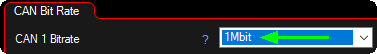
can settings
PDM can bitrate
Sets the PDM CAN communication speed.
•500 kbit (default)
•1 mbit
How to change PDM CAN communication speed.
1. Make sure you have PDM communication with the ECU (verify PDM RealTime Data values).

2. Change the PDM communication bitrate in PDM --> PDM settings, CAN settings.
3. Change the ECU CAN communication speed.
4. Power cycle both PDM and the ECU.
5. Now the ECU and PDM should be communication with each other using the same communication speed.
PDM ID
Sets the PDM ID of the current unit.
•PDM1 (default)
•PDM2
Note: Cannot be set with 2 PDM units connected!