In such case that MaxxECU does not support your trigger system, whether it is for the crank or home/cam, MaxxECU have built-in tools (Diagnostics --> Trigger logger and Diagnostics --> Trigger oscilloscope) to capture these signals to be sent for us for implementations.
Make sure MaxxECU does not support your trigger system by reviewing this page <-- compare your Trigger logger output with our trigger logger example outputs).
How to capture Trigger data for MaxxECU trigger implementations.
It is the same procedure to capture trigger signals regardless if it is from the crank, home/cam or to a VVTi system.
Before proceeding with this, please make sure you fully understand the concept of our trigger system by reading the following two chapters
MaxxECU has a built-in tools for trigger diagnostics:
 | Trigger Oscilloscope <-- Please read and understand this tool before continuing. |
| Trigger Logger <-- Please read and understand this tool before continuing. |
1. Activate inputs on the relevant wired input
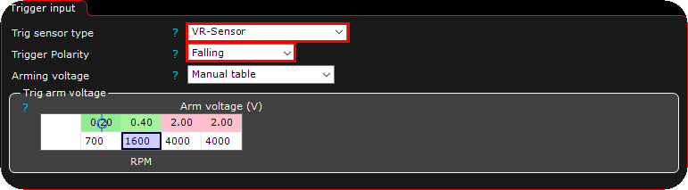
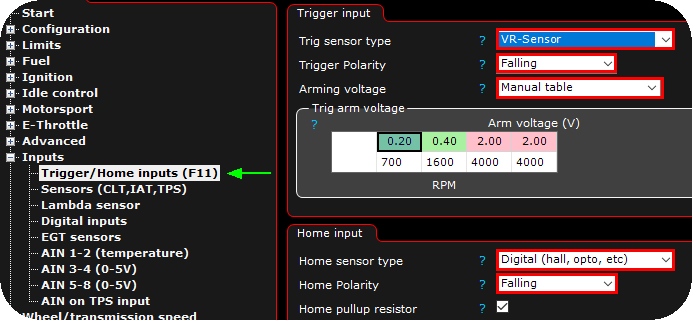
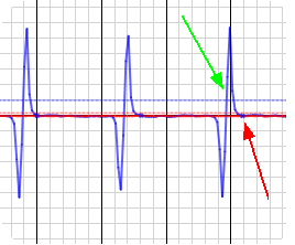
A VR sensor is activated on the TRIGGER input, with the trigger polarity set to falling and with default arming voltages.
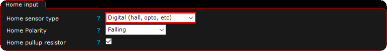
In this example a digital sensor is wired to the HOME/CAM input.
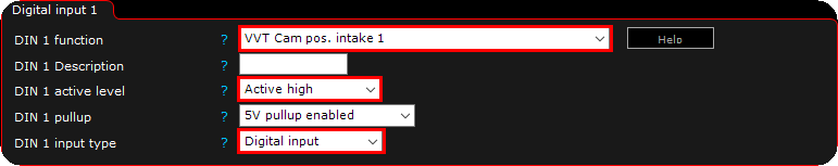
Another example of a digital sensor connected to a digital input as a cam position sensor to the VVTi system.
Note: In the above examples,we don't know how to set anything except the trig sensor type, which must be set accordingly.
Important side note
•Trigger polarity Falling = Active level Low
•Trigger polarity Rising = Active level High
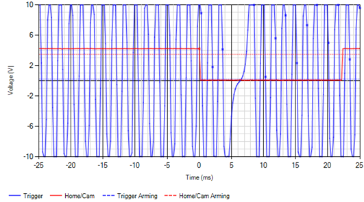
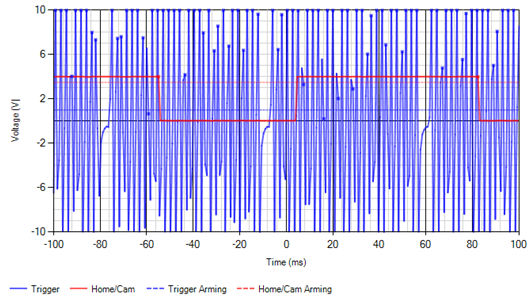
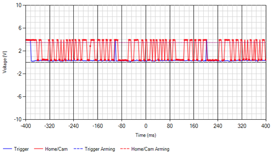
2. Check input signals and determine trigger polarity/active level and arming voltages.
Done by using Diagnostics --> Trigger oscilloscope, and explain above.
MTune built-in tool for trigger diagnostics.
3. If you know the trigger system (missing tooth 60-2 etc), just set that.
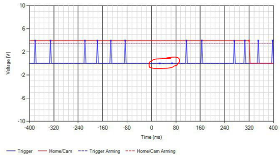
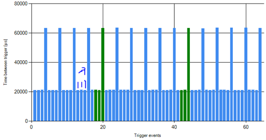
4. Bring us a trigger logger which represent the actual trigger pattern + real picture of the trigger wheel.

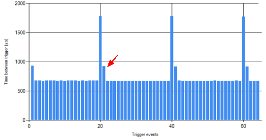
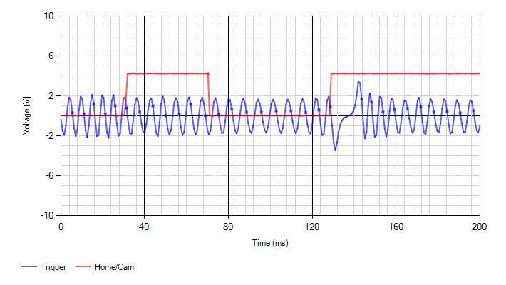
Trigger logger: A good provided trigger wheel which in this case represent a 6-2 pattern.
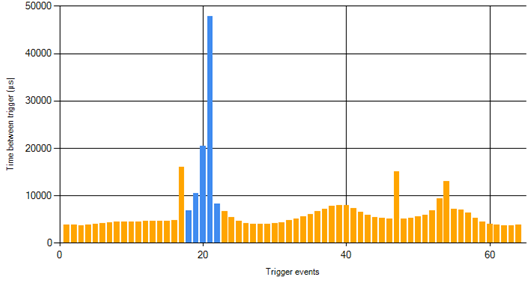
Note: If the pattern here looks irregular or has spikes and gaps in it, there's no way for the ECU to "sync" to the pattern and register RPM. Before continuing and trying to set up the trigger system (60-2 etc), we would need to figure out what the problem with the input signal is.
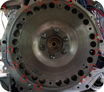
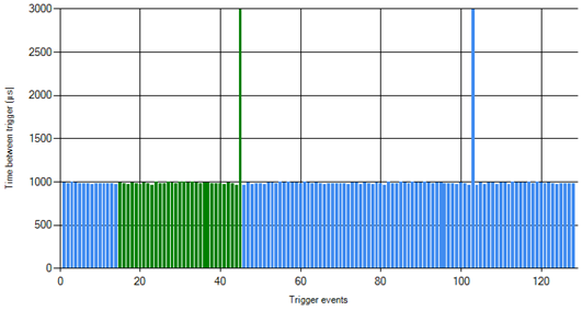
Trigger wheel image: If it's an odd pattern, having pictures of the actual trigger wheel could be necessary too. The pattern above actually has a wheel looking like this. This is obviously not a normal 6-2 wheel, it's 18-2-2-2, a trigger what would require a custom implementation...
Summary
In short, we need the following to create a custom trigger implementation:
1.A trigger logger image which represent the trigger pattern on the actual trigger wheel.
2.An image of the actual trigger wheel to confirm the pattern.