The MaxxECU RACE adapter for Ford Focus with ME 9.0 ECUs can only be used with MaxxECU RACE.
Vehicle cover list
Vehicle |
Engine code |
Year |
LSU sensor |
Note |
Ford Focus RS MK2 |
JZDA |
2009 - 2011 |
Uses stock wideband LSU 4.2 sensor |
|
Ford Focus RS500 MK2 |
JZDA |
2010 - 2011 |
Uses stock wideband LSU 4.2 sensor |
|
Ford Focus ST/ST225 MK2 |
HYDA |
2005 - 2012 |
Uses stock wideband LSU 4.2 sensor |
Note: Manual transmission only!
Control options
Options |
OEM ECU PIN |
MaxxECU IO |
RACE |
Note |
AC magnetic clutch |
|
GPO 1 |
Yes |
|
Boost solenoid (OEM) |
|
GPO 3 |
Yes |
|
VVT solenoid (intake) |
|
GPO 4 |
Yes |
|
Fuel pump relay |
|
GPO 5 |
Yes |
|
Engine FAN (PWM) |
|
GPO 6 |
Yes |
|
VVT solenoid (exhaust) |
|
GPO 7 |
Yes |
|
E-Throttle |
|
GPO 11/12 |
Yes |
|
Tachometer |
|
Yes |
|
|
Tank ventilation valve |
|
INJ 6 |
Yes |
|
Shift solenoid (4-5) |
|
INJ 7 |
Yes |
|
Fuel pressure sensor |
|
AIN 3 |
Yes |
|
Knock sensors (OEM) |
|
KNOCK1/KNOCK2 |
Yes |
|
AC pressure sensor |
|
AIN 7 |
Yes |
|
Clutch switch |
|
YES |
|
|
Vehicle speed (VSS) |
|
Yes |
|
|
EPC light |
|
Yes |
|
|
Instrument cluster/ABS |
|
Yes |
|
|
Fuel consumption |
|
- |
|
|
Oil pressure switch |
|
DIN 4 |
Yes |
Connected to oil level warning lamp in dash using CAN |
Check engine light |
|
Yes |
||
Oil pressure warning |
Yes |
|
||
Bluetooth (MDash) |
|
- |
Yes |
|
EGT option |
|
- |
Yes, direct |
6 EGT direct in harness |
OEM EGT-sensors |
- |
3-pin extra connector (Flex fuel sensor)
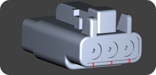
Seen from the wire side of the pre-wired connector.
Pin |
Description |
1 |
+12V power supply |
2 |
Sensor GND |
3 |
DIN 5 (sensor signal) |
16-pin extra connector
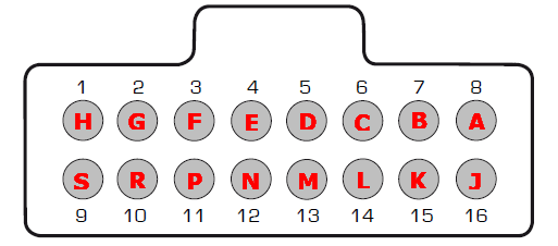
Note: Pinout is from the wire side of the supplied connector.
Pin |
Description |
Usage |
Note |
1 (H) |
+5V sensor supply |
|
|
2 (G) |
Sensor GND |
|
|
3 (F) |
TPS AIN |
|
|
4 (E) |
AIN 4 |
|
|
5 (D) |
|
|
|
6 (C) |
AIN 1 |
|
|
7 (B) |
AIN 2 |
|
|
8 (A) |
AIN 8 |
|
|
9 (S) |
INJ 8 |
|
|
10 (R) |
- |
|
|
11 (P) |
- |
|
|
12 (N) |
+12V power supply |
Output at ignition on |
|
13 (M) |
Engine GND |
|
|
14 (L) |
- |
|
|
15 (K) |
GPO 15 (+12V) |
+12V output |
|
16 (J) |
GPO 16 (+12V) |
+12V output |