In outputs --> Output Config, all output configurations is made.
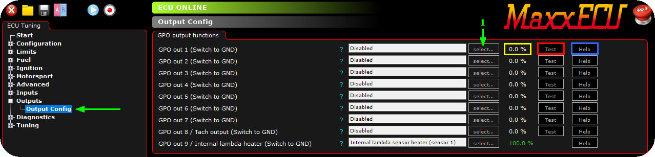
1. Press the Select... button, a new dialog will appear.
Yellow marked box: The actual duty on the relevant output as this moment. <-- good for fault finding an output, does it really output something depending on your settings.
Red marked box: A test feature which can be used to test a certain output without having the output assigned to something. Press the Test button, and the output will be on (100% duty) for ~0.8seconds.
Blue marked box: Direct help of the assigned output feature you have selected.
Note: It is the same step regardless of which output you are working with, like GPO, INJ or IGN and in the above wexample we assign an output to a GPO.
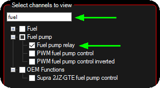
2. Select the output you want to dedicate to this output, confirm by pressing the OK button in the dialog.
In the above example, we searched for "fuel" since we have wired an fuel pump using a relay to the GPO 1.
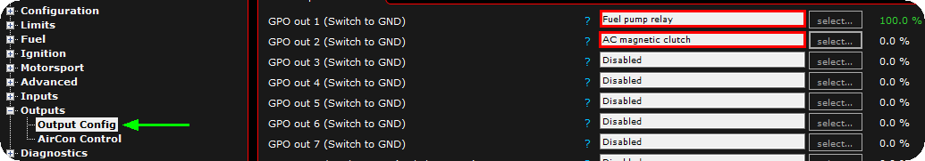
3. Since the fuel pump relay output does not have any extra settings, a new settings page will not be showed, instead in the above example we also dedicated an AC magnetic clutch to GPO 2, and settings for the output is now visible in the Outputs and labeled AirCon Control.
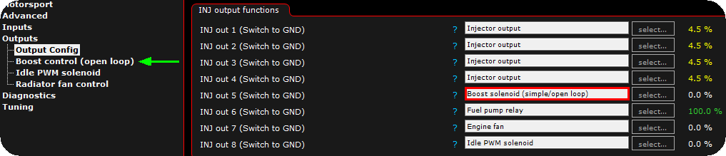
In the above example, we have wired a four injectors to on INJ 1-4, a boost solenoid on INJ 5, a fuel pump relay on INJ 6, a engine fan relay on INJ 7 and a idle solenoid on INJ 8.
Note: This is just examples configurations, there is no need to use the INJ output on low current peripherals as the above, but to show you the flexibility of MaxxECU, it is a good example. Also note that if outputs are set to Injectors or ignitions, the Test button does not exist for safety reasons, use the Diagnostics --> Output test feature instead.
Virtual outputs
Any output system can be assigned to a RT-value that can be used for CAN outputs, tables etc.
Example
You have an external CAN controller which controls your engine FAN.

1. Activate Radiator FAN 1 on Virtual Output 1 function.
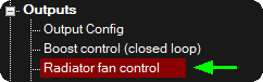
2. The setting page for the radiator fan control is now visible in the configuration tree, set everything accordingly to suit your need.
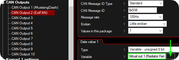
3. Head over to CAN Bus --> CAN Outputs, and enable a User CAN output, set the variable to the created Virtual Out 1. Set ID, rate, endian and values in package as your external CAN controller suggests.
By doing this, no physical output needs to be selected as a function to be able to use a function for external control.
Virtual outputs, can of be used together with for example Bit builder channels.