MaxxECU GEN2 do not have this input, see Pulse inputs.
MaxxECU GEN1 has digital inputs (DIN x) that can be used to trigger certain Digital input functions.
Note: User CAN inputs, AIN x can also be used to trigger digital input functions. All digital inputs tolerate up to +12 V without damage.
Digital Input (DIN x)
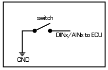
Example wiring to ground a DIN x (with pullup activated) or AIN (temperature) (since these AIN (temp) have built-in pullup they can be triggered when grounded.
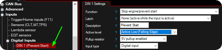
Example MTune setting for a wired digital input 1 switch which will trigger the digital input function Stop engine/prevent start.
Using AIN (temperature) as digital input
Example wiring to ground a DIN x (with pullup activated) or AIN (temperature) (since these AIN (temp) have built-in pullup they can be triggered when grounded.
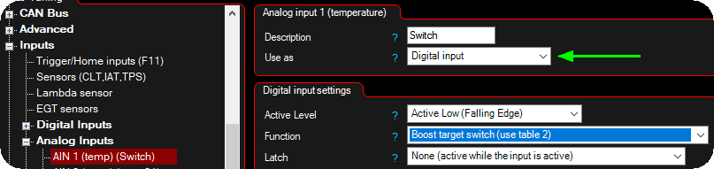
In the above example a simple switch is connected between GND and AIN 1 to close the circuit and activates the secondary boost target in boost control.
Using AIN (0-5V) as digital input
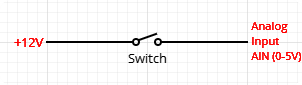
Example wiring to trigger a digital input function on a AIN (0-5V) input.
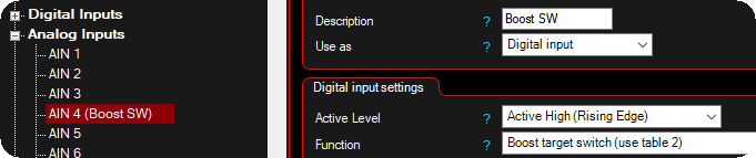
You can also use an AIN (0-5V) to trigger a digital input by wiring a +5V or +12V source through a switch to a AIN (0-5V) input.
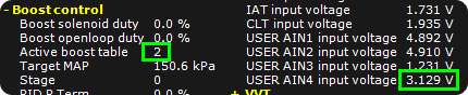
In the above example where we set AIN 4 active level to active high, the boost target changes to boost target 2.
Function
Specifies the digital input function to trigger when the input gets active.
Function 2
Specifies the digital input function to trigger as function 2 when using the below latch function.
latch
Adds a latching feature of the digital input, with possibility to trigger a secondary digital function.
•None (active while the input is active)
•Push: on, Push: off
•Push: on, long Push: off
•Push: on, long Push: function 2 on, push: both off
Note: Long-push = 0.5seconds.
Description
User-defined name for this input to easily identify what's connected.
Active level
Specifies whether function is active when voltage goes from high to low (falling edge) or low to high (rising edge).
Pullup
Specifies whether to use internal pullup resistor (1.0 kOhm to +5V) on selected input to trigger input when connected to ground. if you do not enable the Pullup on this input, you must either input +5V or +12V to trigger it.
Note: Not available on all ECUs and only available when set to digital input.
Input type
Specifies the type (hall or VR) of sensor wired to the input and the actual thresholds used.
•Digital input - +3,3 to +3,5V square wave signal is required to trigger input when set to digital input (up to 10kHz).
•VR input - Requires a - 0,16V to +0,16V (0,32V peak-peak) signal to trigger input when set to VR (up to 10kHz).
Note: Not available on all ECUs.
Also, see wiring information - Digital inputs.
Digital inputs available in MaxxECU
•Advanced warning system, enable
•Advanced Warning System, Enable Cut
•After launch power limit disable
•Auto transmission gear selector
•Auto transmission lockup enable
•Auto transmission manual mode switch
•Auto transmission, enable WOT RPM shift
•Auto transmission, switch to 2nd shift table
•BMW MS 43 Steering Wheel Buttons
•Brake pedal/stop light active
•Edge-triggered pulse output X trigger input
•Electric waterpump override input
•E-Throttle Volvo backup pedal position (PWM)
•E-Throttle Volvo main and backup pedal position (PWM)
•Extra fuel table X table activation switch
•Extra ignition table X table activation switch
•Extra fuel/ign table activation switch (all)
•FAN + Electric waterpump override input
•Fuel adaptation, enable adaptation
•Hella coolant pressure and temperature sensor
•Hella oil pressure and temperature sensor
•Hella User pressure and temperature sensor
•Launch control switch, enable stage
•Logging, reset and start new file
•Power management system disable
•Power management system enable
•Rolling launch control switch
•RPM limit, use secondary limit RPM
•RPM limit, use secondary mode
•Speedsensor transmission input shaft RPM
•Speedsensor wheelspeed front/rear right/left
•Transmission Clutchkick/burnout mode (8HP)
•Transmission Converter Slip Request
•Trigger, HOME+CAM dual sensor, cam sensor
•Tripmeter, use Tripmeter 2/ fuel used 2
•Vehicle speed sensor VSS (simple)
•Virtual fuel tank reset level
•Water/Methanol injection, enable
•Water/Methanol Injection, low-level sensor
•Wheel setup (use setup 2 when active)
How to make digital input 3 (DIN 3) visible?
MaxxECU V1/RACE and PRO (REV4+) has the ability to use GPO 7 as digital input 3 (DIN 3).
Note: The GPO7/DIN3 has a fixed +5V pullup.
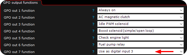
GPO 7 used as digital input 3 (DIN 3) in the above example in Output --> Output config.

In Inputs --> Digital inputs, DIN 3 is now available for usage in MaxxECU.
Video tutorial

Where is MaxxECU DIgital input 3 (DIN 3)